INSTALLATION
QUICK-START
A typical system will use an IR receiver, several emitters, and a power supply all connected to a connecting block.
1. Connect the IR receiver to the “IR RCVR” port on the connecting block. The ‘red’ connector is installed to the ‘red’ plug.
Note: In some extended distances, additional
2.Connect the Emitters to the connecting block. The ‘yellow’ connector is installed to the ‘yellow’ plug.
3.Connect the power supply to the connecting block.
4.Installation complete
MOUNTING
Drill a 1/2” hole in any surface, such as a cabinet panel. Pass the lead and the body of the ML85 through the hole and secure from the rear with the nut (supplied).
LOCAL SYSTEM APPLICATION
In this system a 283D
ML Series | 781ERGPS |
|
|
| Satellite Receiver |
IR Receivers IR Photodiode |
|
|
|
| |
|
|
|
|
| |
Talkback LED | To 120 VAC |
|
|
| |
(unswitched) |
|
| 283D Emitter | ||
|
|
| |||
Hand Held |
| DVD | |||
Connecting Block | |||||
Remote |
|
|
|
|
|
| 12VDC |
| EMITTERS | 283D Emitter | |
| IR RCVR | ® |
| ||
| +12 VDC |
|
|
| A/V Receiver |
| GND |
|
|
| |
| STATUS |
|
|
|
|
| IR IN |
|
|
|
|
|
|
|
|
| 283D Emitter |
CABLE CONNECTIONS
ML85s may also be used where the
2
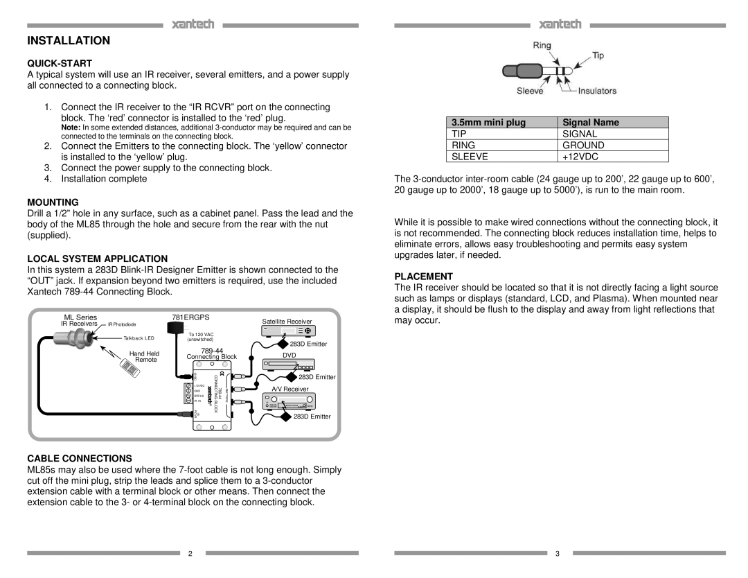
3.5mm mini plug | Signal Name |
TIP | SIGNAL |
RING | GROUND |
SLEEVE | +12VDC |
The
While it is possible to make wired connections without the connecting block, it is not recommended. The connecting block reduces installation time, helps to eliminate errors, allows easy troubleshooting and permits easy system upgrades later, if needed.
PLACEMENT
The IR receiver should be located so that it is not directly facing a light source such as lamps or displays (standard, LCD, and Plasma). When mounted near a display, it should be flush to the display and away from light reflections that may occur.
3