PA4100X, FOUR CHANNEL HI-POWER AMPLIFIER specifications
The Xantech PA4100X Four Channel Hi-Power Amplifier stands out as a robust solution for those seeking high-fidelity audio performance across multiple channels. This amplifier is engineered to deliver superior sound quality and reliable performance, making it an ideal choice for both residential and commercial audio applications.One of the main features of the PA4100X is its impressive power output. With a total of 100 watts per channel at 4 ohms and 70 watts at 8 ohms, this amplifier is capable of driving a variety of speakers, ensuring that users can enjoy rich, immersive audio without distortion, even at higher volume levels. This makes it particularly suitable for environments where sound clarity and volume are paramount, such as in restaurants, retail spaces, or home theaters.
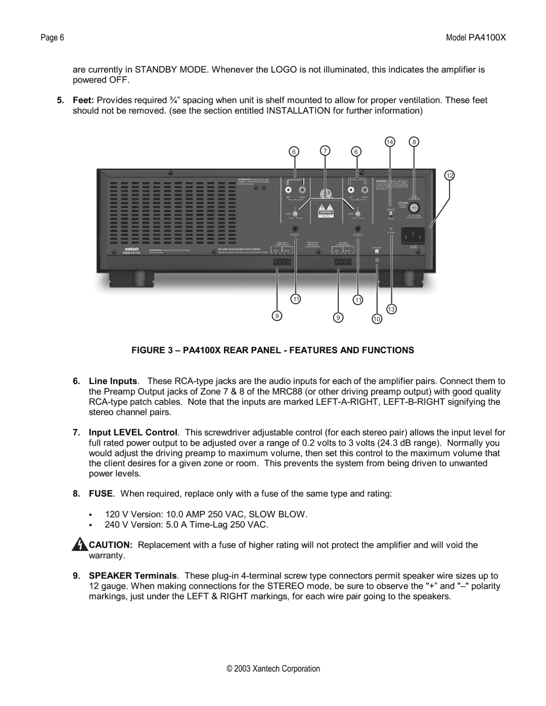
The PA4100X employs sophisticated technologies that enhance audio performance. It includes built-in protection circuitry that safeguards the amplifier from overheating and short-circuiting, ensuring longevity and reliability. The unit features a comprehensive array of inputs and outputs, allowing seamless integration with other audio components. It supports both unbalanced and balanced connections, providing versatility for different setup configurations.
Another key characteristic of the PA4100X is its compact and sturdy design. The unit is housed in a durable chassis that not only withstands the rigors of daily use but also integrates well with existing audio setups. Its straightforward controls and indicators make it user-friendly, allowing for easy adjustments and monitoring of performance.
Additionally, the amplifier offers efficient cooling solutions, including a fan that operates quietly, ensuring that the unit remains at optimal operating temperatures without adding noise to the listening experience. The PA4100X is equipped with advanced features like adjustable gain controls for each channel, facilitating precise audio balancing and customization based on the listener's preferences.
Overall, the Xantech PA4100X Four Channel Hi-Power Amplifier is a versatile and powerful audio solution designed for those who demand high-quality sound performance across multiple channels. Its combination of features, advanced technologies, and user-friendly design makes it an excellent choice for a wide range of audio applications, where clarity, power, and reliability are essential.

