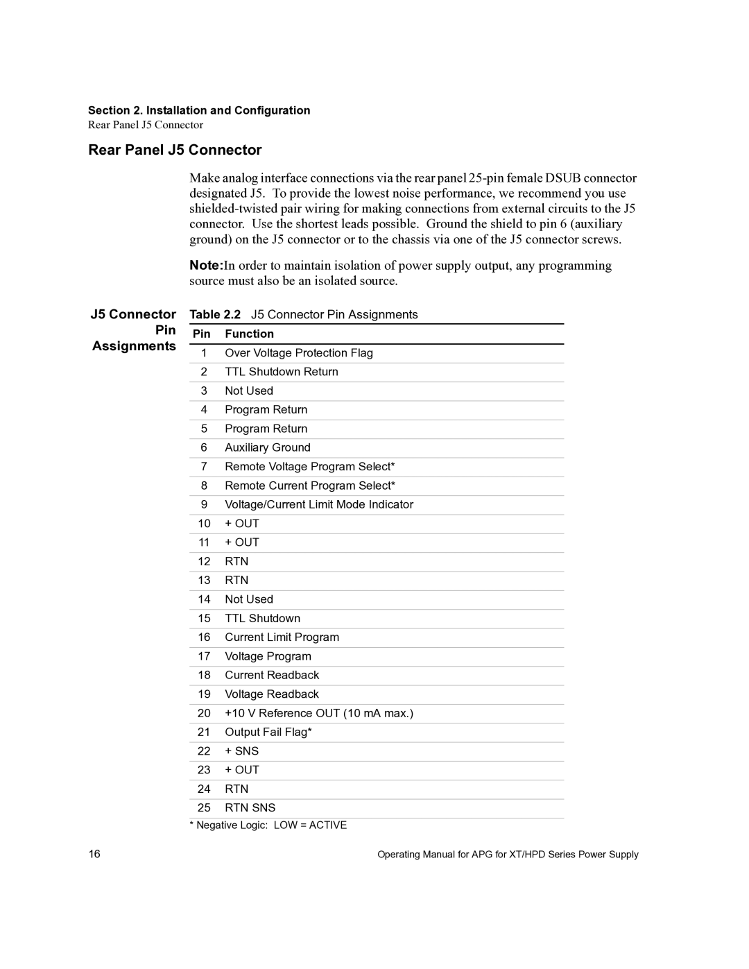
APG-HPD, APG-XT specifications
Xantrex Technology has established itself as a leader in providing innovative power solutions, and its APG-XT and APG-HPD series are prime examples of this commitment. These advanced power supplies are designed for a variety of applications, catering especially to industries that require reliable and high-performance power management systems.The APG-XT, or Advanced Power Generation - Xtended Technology, is engineered for versatility in challenging environments. It offers a compact design and lightweight structure while maintaining robust performance. Key features include a wide input voltage range, enabling it to handle fluctuations in power supply without compromising output stability. Advanced thermal management technologies ensure optimal operation even at elevated temperatures, making this power supply suitable for demanding applications in sectors such as telecommunications, transportation, and renewable energy.
Another notable attribute of the APG-XT is its modularity. Users can customize the power output based on specific load requirements, allowing for flexible deployment in various scenarios. The integrated communication protocols facilitate real-time monitoring and control, providing users with essential data that can improve system efficiency and reliability. Safety features such as short-circuit protection, over-voltage protection, and thermal overload protection are integral to its design, ensuring safe operation under all load conditions.
The APG-HPD, or Advanced Power Generation - High Power Density, takes this reliability a step further by delivering a higher power output while maintaining efficiency. This model is particularly suited for applications that demand significant power in a smaller footprint. With its high-density architecture, it can significantly reduce the space required for installation without sacrificing performance. Like its counterpart, it also features advanced thermal regulation and safety mechanisms that keep the system stable under various operational conditions.
Both models incorporate the latest digital technology, enhancing their performance and user interface. The intuitive display interface allows users to easily access system data and parameters, simplifying the monitoring process. With remote access capabilities, users can control and adjust settings from afar, making the APG-XT and APG-HPD ideal for remote locations or systems that require minimal human intervention.
In conclusion, Xantrex Technology's APG-XT and APG-HPD power supplies offer an impressive combination of reliability, efficiency, and user-friendly features. Their state-of-the-art technologies make them well-suited for demanding applications across multiple industries, ensuring that users have a robust power solution they can depend on.

