Manuals
/
Xilinx
/
Computer Equipment
/
Computer Hardware
Xilinx
ML510
quick start
Software Setup
Models:
ML510
1
12
43
43
Download
43 pages
12.98 Kb
9
10
11
12
13
14
15
16
Additional Setup Details
PowerPC
Memory Solutions
Page 12
Image 12
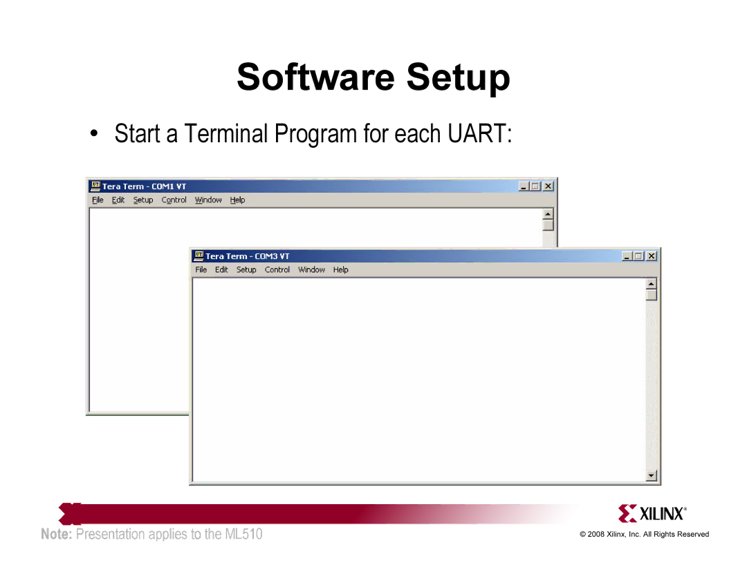
Software Setup
•
Start a Terminal Program for each UART:
Note:
Presentation applies to the ML510
Page 11
Page 13
Page 12
Image 12
Page 11
Page 13
Contents
ML510 QuickStart
Overview
ML510 BSB DIMM0 Hardware
ML510 MicroBlaze design hardware includes
ML510 PPC440 design hardware includes
ML510 BSB DIMM1 Hardware
ML510 BSB DIMM1 Hardware
ML510 Dual Processor Hardware
ML510 Dual Processor design hardware includes PPC4400
Additional Setup Details
Refer to ml510overviewsetup.ppt for details on
Hardware Setup
Hardware Setup
USB Keyboard
Software Setup
Factory CompactFlash
Network Setup
CompactFlash Setup
Equipment Setup
ACE-Loader
CF1 TestApp Peripheral
CF2 VxWorks DIMM0
CF3 TestApp Peripheral
CF4 VxWorks DIMM1
CF5 Dual VxWorks
CF6 My ACE
CF7 Slideshow
Slideshow
Documentation
Documentation
Virtex-5 RocketIO
Design Resources
Additional Design Resources
Platform Studio
PowerPC
MicroBlaze
Memory Solutions
ChipScope Pro
Ethernet
PLB v4.6 IP
Documentation
XPS 16550 Uart DS577 PLBV46 to DCR Bridge Data Sheet DS578
LMB Block RAM Interface Controller Data Sheet DS452
Documentation
ML510
ML510 Schematics ML510 Bill of Material
Top
Page
Image
Contents