IMPORTANT
1.READ ALL THESE INSTRUCTIONS & WARNINGS FULLY BEFORE COMMENCING INSTALLATION.
2.INSTALLATIONS AND WIRING MUST CONFORM TO CURRENT IEE REGULATIONS (UK), LOCAL OR APPROPRIATE REGULATIONS (OTHER COUNTRIES). IT IS THE INSTALLER’S RESPONSIBILITY TO ENSURE THAT THE APPROPRIATE BUILDING CODES OF PRACTICE ARE ADHERED TO.
3.A QUALIFIED ELECTRICIAN MUST SUPERVISE ALL INSTALLATIONS.
4.THESE APPLIANCES ARE INTENDED FOR CONNECTION TO FIXED WIRING.
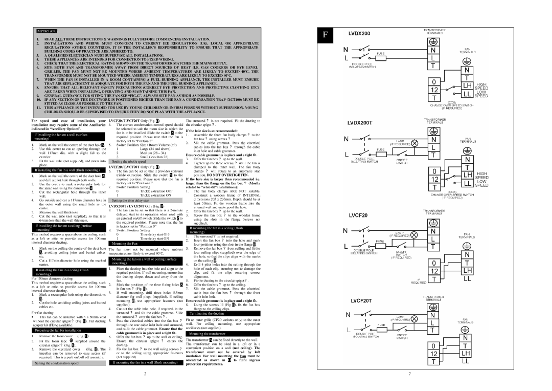
5.CHECK THAT THE ELECTRICAL RATING SHOWN ON THE TRANSFORMER MATCHES THE MAINS SUPPLY.
6.SITE BOTH FAN AND TRANSFORMER AWAY FROM DIRECT SOURCES OF HEAT (I.E. GAS COOKERS OR EYE LEVEL GRILLES. THE FAN MUST NOT BE MOUNTED WHERE AMBIENT TEMPERATURES ARE LIKELY TO EXCEED 40ºC. THE TRANSFORMER MUST NOT BE MOUNTED WHERE AMBIENT TEMPERATURES ARE LIKELY TO EXCEED 40ºC.
7.WHEN THE FAN IS INSTALLED IN A ROOM CONTAINING A FUEL BURNING APPLIANCE, THE INSTALLER MUST ENSURE THAT AIR REPLACEMENT IS ADEQUATE FOR BOTH THE FAN AND THE FUEL BURNING APPLIANCE.
8.ENSURE THAT ALL RELEVANT SAFETY PRECAUTIONS (CORRECT EYE PROTECTION AND PROTECTIVE CLOTHING ETC) ARE TAKEN WHEN INSTALLING, OPERATING AND MAINTAINING THIS FAN.
9.GENERAL GUIDANCE FOR SITING THE FAN SEE “FIG.G”. ALWAYS SITE FAN AS HIGH AS POSSIBLE.
10.IF ANY SECTION OF THE DUCTWORK IS POSITIONED HIGHER THAN THE FAN A CONDENSATION TRAP (XCT100) MUST BE FITTED AS CLOSE AS POSSIBLE TO THE FAN.
11.THIS APPLIANCE IS NOT INTENDED FOR USE BY YOUNG CHILDREN OR INFIRM PERSONS WITHOUT SUPERVISION. YOUNG CHILDREN SHOULD BE SUPERVISED TO ENSURE THEY DO NOT PLAY WITH THE APPLIANCE.
For speed and ease of installation, your installation may require some of the Ancillaries indicated in “Ancillary Options”.
If installing the fan on a wall (surface mounting)
1.Mark on the wall the centre of the duct hole .
.
2.Use this centre to cut an opening through the wall 117mm dia. with a slight fall to the exterior.
3.Fit the wall tube (not supplied), and motar into place.
If installing the fan in a wall (flush mounting)
1.Mark on the wall the centre of the duct hole  , and drill a pilot hole through both walls.
2.Use the centre to mark a rectangular hole for the inner wall using the dimensions .
.
3.Cut the rectangular hole through the inner wall.
4.Go outside and cut a 117mm diameter hole in the outer wall using the small hole as the centre.
5.Measure the wall thickness.
6.Cut the wall tube (not supplied), so that it is 64mm less than the wall thickness.
If installing the fan on a ceiling (surface mounting)
This method requires a space above the ceiling, such as a loft or attic, to provide access for 100mm internal diameter ducting.
1.Mark on the ceiling the centre of the duct hole  , avoiding ceiling joists and buried cables etc.
2.Cut a 117mm diameter hole using the marked centre.
If installing the fan in a ceiling (flush mounting)
For 100mm diameter ducting:
This method requires a space above the ceiling, such as a loft or attic, to provide access for 100mm internal diameter ducting.
1.Mark a rectangular hole using the dimensions  .
.
2.Cut the hole, avoiding ceiling joists and buried cables etc.
For flat ducting:
∙This fan can be installed within a 50mm void without the circular spigot ? (Fig.  ). Flat ducting adapter kit (FDA) available.
Preparing the fan for installation
1.Remove the front cover • (Fig.  )
)
2.Fit the foam tape  supplied around the circular spigot ? (Fig.
  ).
).
3.Remove the electrical cover • (Fig.  ). The impeller can be removed to ease access (if required). This is a push on/pull off assembly.
Setting the condensation speed
LVCF20 / LVCF20T Only (Fig. )
4.The correct condensation control speed should be selected to suit the room size in which the fan is to be installed. Slide the switch  to the required position. Please note that the fan is factory set to “Position 2”.
5.Switch Position Size / Room Volume (m³)
1Large (34 and above)
2Medium (28 – 34)
3Small (less than 28)
Setting the trickle speed
LVCF20 / LVCF20T Only (Fig. )
6.The fan can be set so that it provides constant trickle extraction. Slide the switch  to the required position. Please note that the fan is factory set to “Position 0”.
7.Switch Position Setting
0Trickle extraction OFF
1Trickle extraction ON
Setting the time delay start
LVDX200T / LVCF20T Only (Fig. )
8.The fan can be set so that there is a 2-minute delayed start to its operation when used with an external on/off switch. Slide the switch  to the required position. Please note that the fan is factory set to “Position 0”
9.Switch Position Setting
0Time delay start OFF
1Time delay start ON
Mounting the Fan
The fan must not be mounted where ambient temperatures are likely to exceed 40°C.
Mounting the fan on a wall or ceiling (surface mounting)
1.Place the ducting into the hole and align to the required position. If wall mounting, ensure that the ducting slopes down and away from the fan.
2.Mark the positions of the three fixing holes  in fan box ? (Fig.
  ).
).
3.If wall mounting, drill three holes 5.5mm diameter for wall plugs (supplied). If ceiling mounting  , use appropriate fasteners (not supplied).
4.Cut out the cable inlet hole, if required, in the surround ? and slit the cable grommet. Slide the surround ? over the fan box ?.
5.Pass the electrical cables into the fan box ? through the rear cable inlet hole and surround, and re-fit the cable grommet. Ensure that the cable grommet is in place and a tight fit.
6.Offer the fan box ? up to the wall or ceiling. Ensure the circular spigot ? enters the ducting.
7.Fix the fan box ? to the wall using screws ? or to the ceiling using appropriate fasteners (not supplied).
If mounting the fan in a wall (flush mounting)
The surround ? is not required. Fit the ducting to the circular spigot ?.
If the hole size is as recommended:
1.Assemble the three fan body clamps ? to the fan box ? using screws ?.
2.Slit the cable grommet. Pass the electrical cables into the fan box ? through the cable inlet hole and cable grommet.
Ensure cable grommet is in place and a tight fit.
3.Offer the fan box ? up to the wall.
4.Tighten up the three screws ? until the fan is clamped to the inner wall. The fan body clamps ? will rotate to an automatic stop position. DO NOT OVERTIGHTEN.
If the hole size is larger than recommended i.e. larger than the flange on the fan box ? (Mostly related to “retro-fit” installations):
1.The fan body clamps ARE NOT suitable. Construct a wooden frame of INTERNAL dimensions 203 x 233mm. Depth should be at least 50mm. Fit the wooden frame into the internal wall and make good the hole.
2.Offer the fan box ? up to the wall.
3.Screw the fan box ? to the wooden frame using the slots in the flange (screws not supplied).
If mounting the fan in a ceiling (flush mounting)
1.The surround ? is not required.
2.Insert the fan box ? into the hole and mark four positions using the slots in the flange  .
.
3.Remove the fan box ? from ceiling and fit the four ceiling clips (supplied) over the edge of the hole, so that the clips align with the marks on the ceiling  .
.
4.Drill 4 pilot holes into the ceiling through the hole of each clip, ensuring not to damage the clip, and fit the clips ensuring correct alignment.
5.Fit the ducting to the circular spigot?.
6.Offer the fan box ? up to the ceiling.
7.Slit the cable grommet. Pass the electrical cable into the fan box ? through the front cable inlet hole.
Ensure cable grommet is in place and a tight fit.
8.Using the screws 11 (Fig  ), fix the fan box flange to the ceiling clips.
Terminating the ducting
Fit an outer grille (CF20 variants only) to the outer wall. For ceiling mounting, use appropriate ancillaries (not supplied).
Mounting the transformer
The transformer  can be fixed directly to the wall. The transformer can be sited in a loft or in a convenient position on a wall (not ceiling). The transformer must not be covered by loft insulation. For wall mounting the Fan must be
orientated as shown in  to fulfil ingress protection requirements.