035-09651-001-A-0304

A 7/8" OD drain connection extends through right hand side of cabinet. Refer to Fig. 7 for recommended drain piping.

The drain connection is located on the same side of the unit as the refrigerant connections. The line should be insulated where moisture drippage will be objectionable or cause damage to the area.

The 3" dimension must equal or exceed the negative static pressure developed by the supply air blower. If it does not, the condensate will not drain properly and may overflow the drain pan. The trap must be at least 2-1/2" deep to maintain a water seal under all operating conditions, especially during blower start-up.

NOTE: The unit may have to be raised off the floor to allow enough height for the trap.

TABLE 3 - SUPPLY AIR BLOWER MOTOR PULLEY ADJUSTMENT

TURNS


MODEL


F3EH090

F3EH090

F4EH120

F4EH120

OPEN*

60 Hz

50 Hz

60 Hz

50 Hz


5

655 RPM

542 RPM

700RPM

581 RPM

4

760

580

750

622

3

745

618

800

663

2

790

656

850

704

1

835

694

900

745

0

880

732

950

786

*Pulleys can be adjusted in half-turn increments.

SUPPLY AIR BLOWER ADJUSTMENT

The RPM of the supply air blower will depend on the required CFM, the unit accessories and the static resistances of both the supply and the return air duct systems. With this information, the RPM for the supply air blower can be determined from the blower performance in Table 4.

Knowing the required blower RPM and the blower motor HP, the setting (turns open) for the supply air motor pulley can be determined from Table 3.

Each motor pulley has:

1.A threaded barrel with two flats (or notched recesses) 180 degrees apart.

2.A movable flange with one set screw.

After the movable flange has been rotated to the proper number of “turns open”, the set screw should be tightened against the flat on the barrel to lock the movable flange in place. If the pulley includes a locking collar, the locking collar must be loosened to adjust the setting of the movable flange.

Note the following:

1.The supply air CFM must be within the limitations shown in Table 2.

2.All pulleys can be adjusted in half turn increments.

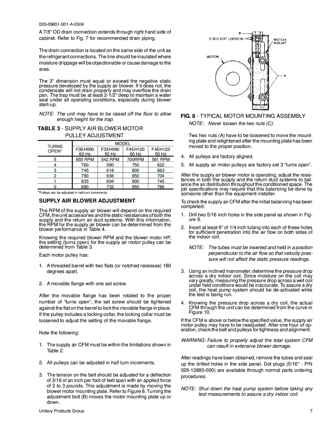
3.The tension on the belt should be adjusted for a deflection of 3/16 of an inch per foot of belt span with an applied force of 2 to 3 pounds. This adjustment is made by moving the blower motor mounting plate. Refer to Figure 8. Turning the adjustment bolt (B) moves the motor mounting plate up or down.

FIG. 8 - TYPICAL MOTOR MOUNTING ASSEMBLY

NOTE: Never loosen the two nuts (C).

Two hex nuts (A) have to be loosened to move the mount- ing plate and retightened after the mounting plate has been moved to the proper position.

4.All pulleys are factory aligned.

5.All supply air motor pulleys are factory set 3 “turns open”.

After the supply air blower motor is operating, adjust the resis- tances in both the supply and the return duct systems to bal- ance the air distribution throughout the conditioned space. The job specifications may require that this balancing be done by someone other than the equipment installer.

To check the supply air CFM after the initial balancing has been completed:

1.Drill two 5/16 inch holes in the side panel as shown in Fig- ure 9.

2.Insert at least 6" of 1/4 inch tubing into each of these holes for sufficient penetration into the air flow on both sides of the indoor coil.

NOTE: The tubes must be inserted and held in a position perpendicular to the air flow so that velocity pres- sure will not affect the static pressure readings.

3.Using an inclined manometer, determine the pressure drop across a dry indoor coil. Since moisture on the coil may vary greatly, measuring the pressure drop across a wet coil under field conditions would be inaccurate. To assure a dry coil, the heat pump system should be de-activated while the test is being run.

4.Knowing the pressure drop across a dry coil, the actual CFM through the unit can be determined from the curve in Figure 10.

If the CFM is above or below the specified value, the supply air motor pulley may have to be readjusted. After one hour of op- eration, check the belt and pulleys for tightness and alignment.

WARNING: Failure to properly adjust the total system CFM can result in extensive blower damage.

After readings have been obtained, remove the tubes and seal up the drilled holes in the side panel. Dot plugs (5/16" - P/N 029-13880-000) are available through normal parts ordering procedures.

NOTE: Shut down the heat pump system before taking any test measurements to assure a dry indoor coil.

Unitary Products Group

7

Page 7
Image 7
York Supply AIR Blower Motor Pulley Adjustment, Supply AIR Blower Adjustment, Turns Model, F3EH090 F4EH120, Open

F3EH090 specifications

The York F3EH090 is a high-efficiency, versatile air conditioning unit designed for residential and light commercial applications. This model is part of the York F3 series, recognized for its advanced engineering and innovative technologies that cater to modern climate control requirements.

One of the main features of the F3EH090 is its energy efficiency. With a high Seasonal Energy Efficiency Ratio (SEER) rating, this unit is engineered to deliver superior cooling while minimizing energy consumption. This not only helps in reducing utility bills but also contributes to a lower carbon footprint, making it an environmentally friendly choice.

In terms of design, the F3EH090 boasts a compact and stylish profile, making it suitable for various installation locations. The unit is equipped with a robust compressor that ensures reliable performance across different weather conditions. The compressor operates quietly, providing a comfortable indoor environment without disruptive noise levels.

The F3EH090 incorporates advanced technologies, including a microprocessor controller that optimizes system performance. This controller monitors various parameters and adjusts operation settings to maximize efficiency and comfort. Additionally, the unit features variable-speed fan motors, which allow for customized airflow levels and enhance overall comfort.

Another significant characteristic of the York F3EH090 is its ease of installation and maintenance. The design allows for straightforward access to components, simplifying routine maintenance tasks. This feature is particularly valuable for service technicians and homeowners alike, as it reduces downtime and contributes to the longevity of the system.

The durability of the F3EH090 is further enhanced by its corrosion-resistant coating, which protects the unit from harsh weather conditions. This feature ensures that the air conditioner remains operational and efficient over its lifespan.

Furthermore, the York F3EH090 is compatible with various smart home technologies, allowing users to integrate the unit into their home automation systems. This compatibility enables remote monitoring and control, promoting convenience and energy savings.

In summary, the York F3EH090 stands out with its impressive energy efficiency, advanced technologies, and ease of maintenance. Designed with modern needs in mind, this air conditioning unit is an excellent choice for anyone looking to enhance their indoor comfort while ensuring environmental sustainability.