271015-UUM-A-0407

HOW YOUR GAS FURNACE WORKS

Your furnace is a very easy appliance to take for granted. Season after season, it sits there in your home, keeping you warm and comfortable. For this reason, you may never have given much thought to the way your furnace operates. In order to get the safest and most efficient oper- ation from your furnace, you should understand how your furnace does its job.

When you set your thermostat to provide more heat in your home, you are starting the heating cycle of the furnace. First, the inducer motor starts to purge the heat exchanger of any remaining gases. Next, the hot surface ignitor glows and after a warm-up period the gas valve opens and ignition occurs. A short time later, the blower starts and dis- tributes the warm air throughout the home. When the temperature set- ting on your thermostat is reached, the gas valve closes, the main burners are turned off, and the blower continues to run until the remain- ing warm air in the system is distributed. When the blower stops, the heating cycle has ended.

START-UP AND SHUTDOWN INSTRUCTIONS

Read the Instructions Below Before Trying to Start the Furnace

If you do not follow these instructions exactly, a fire or explosion may result causing property damage, personal injury, and/or loss of life.

A.This appliance does not have a pilot. It is equipped with an ignition device which automatically lights the burner. Do not try to light the burner by hand.

B.BEFORE OPERATING; smell all around the appliance area for gas. Be sure to smell next to the floor because some gas is heavier than air and will settle on the floor.

C.Use only your hand to push the gas control switch to the “on” posi- tion. Never use tools. If the switch will not operate by hand, don’t try to repair it, call a qualified service technician. Force or attempted repair may result in a fire or explosion.

D.Do not use this appliance if any part has been under water. Imme- diately call a qualified service technician to inspect the appliance and to replace any part of the control system and any gas control, which has been under water.

Operating Instructions:

1.STOP! Read the safety information above.

2.Set the thermostat to the lowest setting.

3.Turn off all electric power to the appliance.

4.Remove burner access panel.

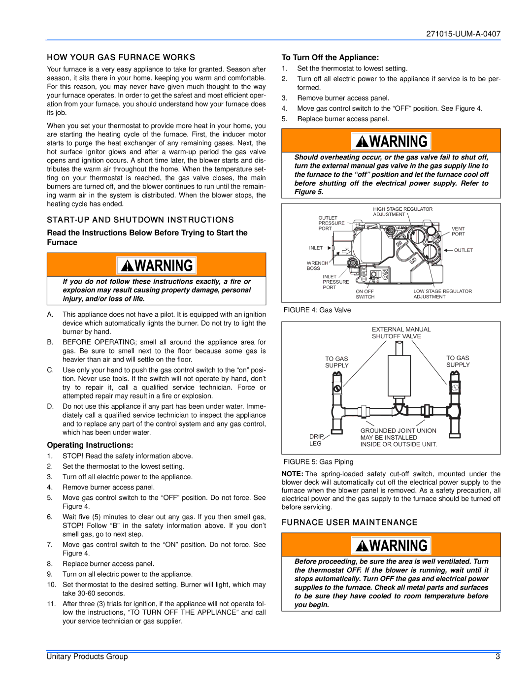
5.Move gas control switch to the “OFF” position. Do not force. See Figure 4.

6.Wait five (5) minutes to clear out any gas. If you then smell gas, STOP! Follow “B” in the safety information above. If you don’t smell gas, go to next step.

7.Move gas control switch to the “ON” position. Do not force. See Figure 4.

8.Replace burner access panel.

9.Turn on all electric power to the appliance.

10.Set thermostat to the desired setting. Burner will light, which may take 30-60 seconds.

11.After three (3) trials for ignition, if the appliance will not operate fol- low the instructions, “TO TURN OFF THE APPLIANCE” and call your service technician or gas supplier.

To Turn Off the Appliance:

1.Set the thermostat to lowest setting.

2.Turn off all electric power to the appliance if service is to be per- formed.

3.Remove burner access panel.

4.Move gas control switch to the “OFF” position. See Figure 4.

5.Replace burner access panel.

Should overheating occur, or the gas valve fail to shut off, turn the external manual gas valve in the gas supply line to the furnace to the “off” position and let the furnace cool off before shutting off the electrical power supply. Refer to Figure 5.

HIGH STAGE REGULATOR

ADJUSTMENT

OUTLET

PRESSURE

PORTVENT

PORT

INLET

OUTLET


WRENCH

BOSS

INLET

PRESSURE

PORT

ON OFF

LOW STAGE REGULATOR

SWITCH

ADJUSTMENT

FIGURE 4: Gas Valve

EXTERNAL MANUAL

SHUTOFF VALVE

TO GAS


TO GAS

SUPPLY


SUPPLY


DRIP


GROUNDED JOINT UNION


MAY BE INSTALLED

LEG


INSIDE OR OUTSIDE UNIT.

FIGURE 5: Gas Piping

NOTE: The spring-loaded safety cut-off switch, mounted under the blower deck will automatically cut off the electrical power supply to the furnace when the blower panel is removed. As a safety precaution, all electrical power and the gas supply to the furnace should be turned off before servicing.

FURNACE USER MAINTENANCE

Before proceeding, be sure the area is well ventilated. Turn the thermostat OFF. If the blower is running, wait until it stops automatically. Turn OFF the gas and electrical power supplies to the furnace. Check all metal parts and surfaces to be sure they have cooled to room temperature before you begin.

Unitary Products Group

3

Page 3
Image 3
York LC8V*DH, PV8*DH, FC8V*DH HOW Your GAS Furnace Works, START-UP and Shutdown Instructions, Operating Instructions

LL8V*DH, LC8V*DH, FL8V*DH, FC8V*DH, PV8*DH specifications

The York FL8V*DH, LC8V*DH, PV8*DH, LL8V*DH, and FC8V*DH series represent a range of advanced heating and cooling solutions tailored to meet the needs of both residential and commercial applications. These units are engineered with cutting-edge technologies that enhance energy efficiency, performance, and user comfort, making them a top choice for HVAC needs.

One of the standout features of these systems is their high-efficiency design, which often exceeds industry standards. The FL8V*DH, for example, boasts an impressive SEER (Seasonal Energy Efficiency Ratio) rating, allowing users to save on energy costs while ensuring optimal heating and cooling comfort. The innovative design minimizes energy consumption without compromising performance, which is critical in today’s eco-conscious market.

Another hallmark of these series is their use of advanced refrigerant technology. Utilizing environmentally friendly refrigerants, such as R-410A, these units deliver excellent heat transfer while reducing the overall carbon footprint. This focus on sustainability ensures that customers can feel good about their choice, contributing positively to the environment.

The technology behind these models extends to their variable-speed blower motors, which provide precise airflow and temperature control. This flexibility allows adjustments based on real-time demand, enhancing comfort and reducing energy usage. The use of smart thermostats with these systems enables users to program schedules, monitor usage, and optimize settings remotely, further improving efficiency.

In terms of durability and reliability, the York series is built from high-quality materials designed to withstand the test of time. Robust construction minimizes maintenance needs, resulting in lower long-term ownership costs. Additionally, many units feature quiet operation technologies, ensuring minimal noise disturbance, which is particularly important in residential settings.

Moreover, installation and servicing of the York FL8V*DH, LC8V*DH, PV8*DH, LL8V*DH, and FC8V*DH systems are made simpler through their user-friendly designs. Easy access points for maintenance staff help to reduce downtime and enhance system longevity.

Overall, the York FL8V*DH, LC8V*DH, PV8*DH, LL8V*DH, and FC8V*DH units stand out due to their efficiency, innovative technology, durability, and user-friendly design, marking them as exceptional choices in the HVAC market. These systems not only provide comfort but also align with energy-saving initiatives, making them a wise investment for the future.