S1-33101975102 specifications
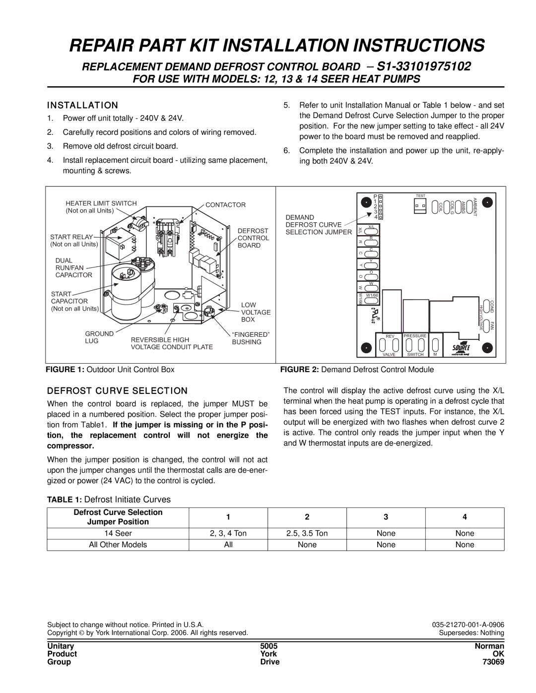
York S1-33101975102 is an advanced air conditioning unit designed to deliver optimal comfort and efficiency in both residential and commercial environments. This model stands out due to its cutting-edge technologies and impressive features that cater to the diverse needs of users.One of the main characteristics of the York S1-33101975102 is its energy efficiency. Utilizing the latest SEER (Seasonal Energy Efficiency Ratio) standards, this unit ensures lower energy consumption while maintaining exceptional cooling performance. This energy efficiency not only translates to cost savings on energy bills but also contributes to a more sustainable environment.
The unit is equipped with a high-performance compressor that enables rapid cooling and heating response times. This feature is particularly beneficial in fluctuating weather conditions, as it helps maintain a consistent indoor temperature. The scroll compressor technology used in the York S1 model is known for its reliability and quiet operation, making it a perfect choice for residential spaces where noise levels must be kept to a minimum.
In addition, the York S1-33101975102 employs a state-of-the-art air filtration system. This system effectively removes dust, allergens, and other airborne particles, ensuring cleaner and healthier indoor air quality. The unit is also designed to provide enhanced humidity control, which is crucial for maintaining comfort and preventing issues related to excess moisture in the air.
Smart technology integration is another standout feature of this model. The York S1-33101975102 can be connected to smart home systems, enabling users to remotely monitor and adjust their settings via smartphone applications. This functionality adds convenience and enhances the overall user experience, allowing for a more personalized approach to indoor climate control.
Durability is a key aspect of the York S1-33101975102's design. Constructed with robust materials and featuring a protective coating, the unit is designed to withstand harsh weather conditions and ensure a longer lifespan. The manufacturer’s comprehensive warranty further reassures customers regarding the longevity and reliability of this air conditioning solution.
In summary, the York S1-33101975102 is a high-performing air conditioning unit that combines energy efficiency, advanced filtration, smart technology, and durable construction. It represents an ideal choice for anyone seeking a reliable and effective cooling solution for their indoor environment.

