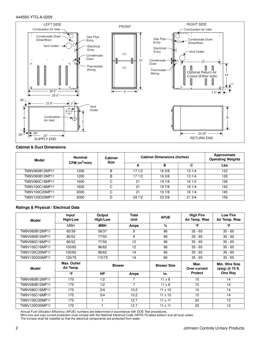
LEFT SIDE |
|
Combustion Air Inlet |
|
Condensate Drain | Gas Pipe |
(Downflow) | Entry |
Vent Outlet | Electrical |
| Entry |
| Condensate |
| Drain |
| Thermostat |
| Wiring |
28.5” |
|
29.5” |
|
.56” |
|
23.8” | 3” |
FRONT |
A |
|
| RIGHT SIDE |
|
|
| Combustion Air Inlet |
|
| Gas Pipe | Condensate Drain |
|
| Entry | (Downflow) |
|
| Electrical |
|
|
| Entry | Vent Outlet |
|
33 | Condensate | 23” |
|
| Drain |
| |
|
|
| |
| Thermostat | Optional Return Air |
|
| Wiring | 14” | |
| Cutout (Either side) | ||
|
| ||
|
|
| |
|
|
| 1” |
|
| 1.5” |
|
Vent |
Outlet |
BCombustion ![]()
Air Inlet | C |
|
.56” |
|
|
| .56” | |
|
|
| |||
|
|
|
| 20” | |
|
|
|
|
| |
SUPPLY END
B
24.25”
RETURN END
Cabinet & Duct Dimensions
| Nominal | Cabinet | Cabinet Dimensions (Inches) | Approximate | |||
Model | Operating Weights | ||||||
CFM (m3/min) | Size |
|
|
| |||
| A | B | C | Lbs | |||
|
|
| |||||
|
|
|
|
|
|
| |
TM9V060B12MP11 | 1200 | B | 17 1/2 | 16 3/8 | 13 1/4 | 122 | |
|
|
|
|
|
|
| |
TM9V080B12MP11 | 1200 | B | 17 1/2 | 16 3/8 | 13 1/4 | 126 | |
|
|
|
|
|
|
| |
TM9V080C16MP11 | 1600 | C | 21 | 19 7/8 | 16 1/2 | 136 | |
|
|
|
|
|
|
| |
TM9V100C16MP11 | 1600 | C | 21 | 19 7/8 | 18 1/4 | 142 | |
|
|
|
|
|
|
| |
TM9V100C20MP11 | 2000 | C | 21 | 19 7/8 | 18 1/4 | 145 | |
|
|
|
|
|
|
| |
TM9V120D20MP11 | 2000 | D | 24 1/2 | 23 3/8 | 21 3/4 | 156 | |
|
|
|
|
|
|
| |
Ratings & Physical / Electrical Data
| Input | Output |
| Total | AFUE | High Fire | Low Fire |
Model | High/Low | High/Low |
| Unit | Air Temp. Rise | Air Temp. Rise | |
|
| ||||||
| MBH | MBH |
| Amps | % | °F | °F |
|
|
|
|
|
|
|
|
TM9V060B12MP11 | 60/39 | 58/37 |
| 9 | 96 | 35 - 65 | 35 - 65 |
|
|
|
|
|
|
|
|
TM9V080B12MP11 | 80/52 | 77/50 |
| 9 | 96 | 35 - 65 | 30 - 60 |
|
|
|
|
|
|
|
|
TM9V080C16MP11 | 80/52 | 77/50 |
| 12 | 96 | 35 - 65 | 35 - 65 |
|
|
|
|
|
|
|
|
TM9V100C16MP11 | 100/65 | 96/62 |
| 12 | 96 | 35 - 65 | 30 - 65 |
|
|
|
|
|
|
|
|
TM9V100C20MP11 | 100/65 | 96/62 |
| 14 | 96 | 35 - 65 | 35 - 65 |
|
|
|
|
|
|
|
|
TM9V120D20MP11 | 120/78 | 115/75 |
| 14 | 96 | 35 - 65 | 35 - 65 |
|
|
|
|
|
|
|
|
| Max. Outlet |
| Blower | Blower Size | Max. | Min. Wire Size | |
Model | Air Temp. |
| (awg) @ 75 ft. | ||||
|
|
|
| ||||
|
|
|
|
|
| Protect | One Way |
| °F | HP |
| Amps | In. | ||
|
|
|
|
|
|
|
|
TM9V060B12MP11 | 170 | 1/2 |
| 7 | 11 x 8 | 15 | 14 |
TM9V080B12MP11 | 175 | 1/2 |
| 7 | 11 x 8 | 15 | 14 |
TM9V080C16MP11 | 175 | 3/4 |
| 10.2 | 11 x 10 | 15 | 14 |
TM9V100C16MP11 | 175 | 3/4 |
| 10.2 | 11 x 10 | 15 | 14 |
TM9V100C20MP11 | 175 | 1 |
| 12.7 | 11 x 11 | 20 | 12 |
TM9V120D20MP11 | 170 | 1 |
| 12.7 | 11 x 11 | 20 | 12 |
Annual Fuel Utilization Efficiency (AFUE) numbers are determined in accordance with DOE Test procedures.
Wire size and over current protection must comply with the National Electrical Code
2 | Johnson Controls Unitary Products |
