Gas Connection |
| |
Connection to the gas supply should be with either rigid |
| |
or |
| |
Connection to the gas supply can be carried out on the |
| |
left or on the right of the hob connection pipe. |
| |
The connection should be suitable for connecting to RC |
| |
1/2 (1/2 BSP male thread). |
| |
When the final connection has been made, it is essential |
| |
that a thorough leak test is carried out on the hob and | FO 0264 | |
installation. | ||
|
Ensure that the main connection pipe does not exert any strain on the hob.
It is important to install the elbow correctly, with the shoulder on the end of the thread, fitted to the
hob connecting pipe.
Failure to ensure the correct assembly will cause leakage of gas.
Electrical connections
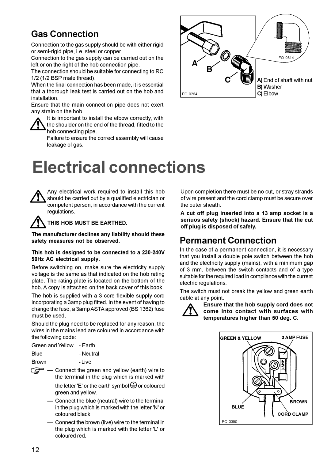
FO 0814
A)End of shaft with nut
B)Washer
C)Elbow
Any electrical work required to install this hob should be carried out by a qualified electrician or competent person, in accordance with the current regulations.
 THIS HOB MUST BE EARTHED.
The manufacturer declines any liability should these safety measures not be observed.
This hob is designed to be connected to a
Before switching on, make sure the electricity supply voltage is the same as that indicated on the hob rating plate. The rating plate is located on the bottom of the hob. A copy is attached on the back cover of this book.
The hob is supplied with a 3 core flexible supply cord incorporating a 3amp plug fitted. In the event of having to change the fuse, a 3amp ASTA approved (BS 1362) fuse must be used.
Should the plug need to be replaced for any reason, the wires in the mains lead are coloured in accordance with the following code:
Green and Yellow - Earth
Blue- Neutral
Brown- Live
Φ— Connect the green and yellow (earth) wire to the terminal in the plug which is marked with
the letter 'E' or the earth symbol![]() or coloured green and yellow.
or coloured green and yellow.
—Connect the blue (neutral) wire to the terminal in the plug which is marked with the letter 'N' or coloured black.
—Connect the brown (live) wire to the terminal in the plug which is marked with the letter 'L' or coloured red.
Upon completion there must be no cut, or stray strands of wire present and the cord clamp must be secure over the outer sheath.
A cut off plug inserted into a 13 amp socket is a seriuos safety (shock) hazard. Ensure that the cut off plug is disposed of safely.
Permanent Connection
In the case of a permanent connection, it is necessary that you install a double pole switch between the hob and the electricity supply (mains), with a minimum gap of 3 mm. between the switch contacts and of a type suitable for the required load in compliance with the current electric regulations.
The switch must not break the yellow and green earth cable at any point.
Ensure that the hob supply cord does not come into contact with surfaces with temperatures higher than 50 deg. C.
FO 0390
12