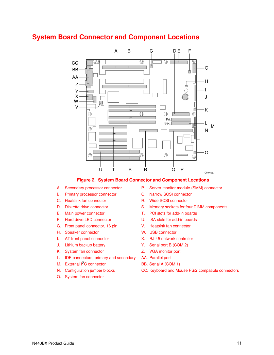
System Board Connector and Component Locations
A | B | C | D E | F |
CC |
|
|
| G |
BB |
|
|
| |
|
|
|
| |
AA |
|
|
| H |
Z |
|
|
| |
|
|
| I | |
Y |
|
|
| |
|
|
|
| |
X |
|
|
| J |
W |
|
|
|
|
V |
|
|
| K |
|
|
|
|
Pri. |
|
|
|
|
|
|
|
|
| L |
| ||
|
|
|
|
|
|
|
|
|
| ||||
Sec. |
|
|
|
|
|
|
|
|
| M | |||
|
|
|
|
|
|
|
|
|
|
|
| N |
|
|
|
|
|
|
|
|
|
|
|
|
|
|
|
|
|
|
|
|
|
|
|
|
|
|
|
|
|
|
|
|
|
|
|
|
|
|
|
|
|
|
|
O
U T S RQ P
OM06957
Figure 2. System Board Connector and Component Locations
A.Secondary processor connector
B.Primary processor connector
C.Heatsink fan connector
D.Diskette drive connector
E.Main power connector
F.Hard drive LED connector
G.Front panel connector, 16 pin
H.Speaker connector
I.AT front panel connector
J.Lithium backup battery
K.System fan connector
L.IDE connectors, primary and secondary
M.External I2C connector
N.Configuration jumper blocks
O.System fan connector
P.Server monitor module (SMM) connector
Q.Narrow SCSI connector
R.Wide SCSI connector
S.Memory sockets for four DIMM components
T.PCI slots for
U.ISA slots for
V.Heatsink fan connector
W.USB connector
X.
Y.Serial port B (COM 2)
Z.VGA monitor port
AA.Parallel port
BB.Serial A (COM 1)
CC.Keyboard and Mouse PS/2 compatible connectors
N440BX Product Guide | 11 |