Poulan 423349 To Replace Mower Blade Drive Belt, To Check Brake, To Replace Motion Drive Belt

Page 23

SERVICE AND ADJUSTMENTS

TO REPLACE MOWER BLADE DRIVE BELT

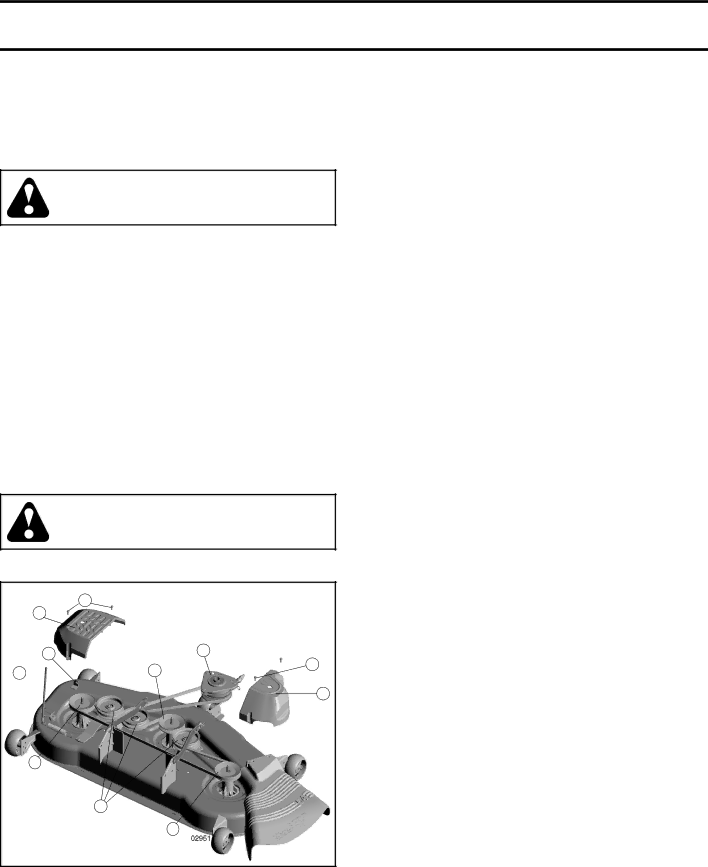
MOWER DRIVE BELT REMOVAL (See Fig. 33)

Park tractor on a level surface. Engage parking brake.

Lower attachment lift lever to its lowest position.

Disengage belt tension rod (K) from lock bracket (L).

CAUTION: Belt tension rod is spring loaded. Have a firm grip on rod and release slowly.

Remove screws (P) from mandrel covers (Q) and re- move covers.

Remove any dirt or grass clippings which may have accumulated around mandrels and entire upper deck surface.

Remove belt from electric clutch pulley (M), both man- drel pulleys (R) and all idler pulleys (V).

MOWER DRIVE BELT INSTALLATION

Install belt around all mandrel pulleys (R) and around idler pulleys (V) as shown.

Install belt onto electric clutch pulley (M).

IMPORTANT: Check belt for proper routing in all mower pulley grooves.

Reassemble mandrel covers (Q). Securely tighten all screws.

Engage belt tension rod (K) on locking bracket (L).

CAUTION: Belt tension rod is spring loaded. Have a tight grip on rod and engage slowly.

Raise attachment lift lever to highest position.

P

Q

LM

TO CHECK BRAKE

If tractor requires more than five (5) feet to stop at highest speed in highest gear on a level, dry concrete or paved surface, then brake must be serviced.

You may also check brake by:

Park tractor on a level, dry concrete or paved surface, depress brake pedal all the way down and engage parking brake.

Disengage transmission by placing freewheel control in “transmission disengaged” position. Pull freewheel control out and into the slot and release so it is held in the disengaged position.

The rear wheels must lock and skid when you try to manu- ally push the tractor forward. If the rear wheels rotate, then the brake needs to be serviced. Contact a qualified service center.

TO REPLACE MOTION DRIVE BELT

(See Fig. 34)

Park the tractor on level surface. Engage parking brake. For assistance, there is a belt installation guide decal on bottom side of left footrest.

BELT REMOVAL -

Remove mower (See “TO REMOVE MOWER” in this section of manual).

NOTE: Observe entire motion drive belt and position of all belt guides and keepers.

• Disconnect clutch wire harness (A).

• Remove anti-rotation link (B) on right side of tractor.

• Remove belt from stationary idler (C) and clutching

idler (D).

• Remove belt from centerspan idler (E).

• Pull belt slack toward rear of tractor. Carefully remove

belt upwards from transmission input pulley and over

cooling fan blades (F).

• Remove belt downward from engine pulley and around

electric clutch (G).

• Slide belt toward rear of tractor, off the steering plate

KR

R

v

P

Q

(H) and remove from tractor.

BELT INSTALLATION -

• Install new belt from tractor rear to front, over the steer-

ing plate (H) and above clutch brake pedal shaft (J).

• Pull belt toward front of tractor and roll belt around

electric clutch and onto engine pulley (G).

• Pull belt toward rear of tractor. Carefully work belt down

around transmission cooling fan and onto the input

pulley (F). Be sure belt is inside the belt keeper.

• Install belt on centerspan idler (E).

R

FIG. 33

• Install belt through stationary idler (C) and clutching

idler (D).

• Reinstall anti-rotation link (B) on right side of tractor.

Tighten securely.

• Reconnect clutch harness (A).

• Make sure belt is in all pulley grooves and inside all

belt guides and keepers.

• Install mower (See “TO INSTALL MOWER” in this sec-

tion of manual).

23

Image 23
Contents Model PBGT26H54II. Slope Operation Safety RulesSafe Operation Practices for Ride-On Mowers General OperationIV. Towing ServiceIII. Children Table of Contents Keys Unassembled PartsMower Mower Front Wheel Slope SheetUnpack Carton AssemblyTools Required for Assembly To Remove Tractor from CartonFirst Install ANTI-SWAY BAR S Install Mower and Drive BeltAssembly Check Brake System Check Tire PressureCheck Deck Levelness Check for Proper Position of ALL BeltsOperation Know Your Tractor Ignition Switch Used for starting and stopping the engineVolt Power Port Used for 12-volt accessories Stopping HOW to USE Your TractorTo USE Cruise Control -J See Fig To Adjust Mower Cutting Height See FigTo Adjust Gauge Wheels See Fig System CharacteristicsTo Transport See Figs Service REMINDER/HOUR MeterReverse Operation System ROS To Operate on HillsTo Start Engine See Fig Before Starting the EngineCheck Engine OIL Level ADD GasolineMowing Tips Schedule MaintenanceMaintenance General RecommendationsTires BatteryTractor Brake OperationEngine Spark Plugs CleaningEngine OIL Filter MufflerTo Level Mower Service and AdjustmentsTo Install Mower To Remove Mower See FigTurn nut right Turn nut left To raise mower To Replace Motion Drive Belt To Replace Mower Blade Drive BeltTo Check Brake To Attach Jumper Cables To Start Engine with a Weak Battery See FigFront Wheel TOE-IN/CAMBER To Remove Wheel for Repairs See FigTo Replace Headlight Bulb To Adjust Throttle Control CableTo Adjust Choke Control To Adjust CarburetorEngine OIL StorageOther Fuel SystemBrake pedal not depressed Depress brake pedal Troubleshooting PointsWeak or dead battery Recharge or replace battery Clean around mandrels to open vent holes Check wiring, switches and connections. If notCorrected, contact an authorized service center Clean underside of mower housingPage Stevens Creek Road Terry Fox Way Augusta, GA 30907 USA Outdoor Products Customer Service DeptHOP Canada contactFold Along This Dotted Line Degree Slope Only Ride UP and Down Hill Not Across Hill Degrees MAXParts and Service Changere DE Pièces LES ET L’ENTRETIEN Degrés MAX Garantie cette de exclus sont normal l’entretien et Dept Service Customer Products OutdoorCanada Au AutoriséPage Connexions les et interrupteurs les câblage, le Vérifiez Dépannage DE GuideLame de mandrin le Remplacez Tordu est lame de mandrin Un Entreposage Carburateur LE Régler Pour Starter DU Commande LA Régler PourGAZ DES Commande LA DE Câble LE Régler Pour Reglages ET Revision34 .FIG AvantRoue LA DE PINCEMENT/CARROSSAGE 36 .FIGDeuse Fig la Voir D’ENTRAÎNEMENT Courroie a L Acer Rempl PourCourroie Acer Rempl Pour Freins LES Vérifier Pour30.FIG 32 .FIG31 .FIG AVANT/ARRIÈRE AjustementTondeuse LA Enlever Pour Tondeuse LA Installer PourFig la Voir Tondeuse LA Niveau LE Ajuster PourDE Plateau DU Lavage DE Raccord Entretien’ALLUMAGE Bougie Fig La Voir CoupeSionmistrans LA DE Moteur Fluide AIR À Filtre’AIR Tamis LE Nettoyer LubrificationEN Fonctionnement DE Système ET Fig la Voir Lame LA EnleverUtilisation Chaque Avant Lubrification DE Tableau22 .FIG UtilisationTondre DE Conseils Transmission LA PurgerQuetimaauto Moteur LE Démarrer Pour’ESSENCE Réservoir LE Remplir Moteur DU D’HUILE Niveau LE VérifierPentes LES Dans Utiliser Pour Accessoires Autres ET Charrettes DES Remorquer Pour’ENTRETIEN/HOROMÈTRE Indicateur 21 et 13 .Fig les VoirJauge DE Roues LES Régler Pour Fig la Voir J- Vitess DE Régulateur LE Utiliser CommentTondeuse LA Utiliser Pour Létrangleur Utiliser Pour Fig la Voir Mentnetionsta DE Frein LE Engager PourReculer Pour ET Avancer Pour 13 .FIG Froid moteur un démarrer de permet Détrangleur Commande NPropriété la de lendommagement et/ou sérieuses Montage LA DE Latéraux Suspension DE Bras LES Fixez 11 .FIG10 .FIG Laté suspension de bras les que vous-Assurez Remarque Courroie LA ET Tondeuse LA InstallerROULIS-ANTI Barre LA D’ABORD Installez Figs les Voir D’ENTRAÎNEMENTPAL LA DE Tracteur LE Retirer Pour DU Tracteur LE Sortir PourLE Pour Exigés Outils LES LA DE Tracteur LE Retirer PourArrières Bielles Montées NON PiécesClés Pente-Guide Roue TondeuseSL-SG-API U1R DimensionSommaire CCA .MIN AMP/HR’ESSENCE DE Sûre Manipulation Général EntretienTracteurs des sécurité toute En l’utilisation pour ConseilsTracteurs des sécurité toute en l’utilisation pour Conseils PentesLES Dans Fonctionnement AUX Imprimé