Operator presence control bar
Upper handle | LIFT UP |
|
LIFT
UP
3 POSITION “QUICK” HANDLES
•Raise lower handle section to operating position and squeeze the bottom ends of lower handle towards each other until the pin in handle can be inserted into one of the three height adjustment holes.
3 POSITION “QUICK”
![]() Handle pin
Handle pin
Mowing SQUEEZE position
Handle
adjustment
Lower handle bracket
3 POSITION “EURO” / “EZ” HANDLES
•Raise lower handle section to operating position and align hole in handle with one of three height positioning holes.
•Insert handle bolt through handle and bracket and secure with knob.
•Repeat for opposite side of handle.
3 POSITION “EURO”
Handle adjustment bracket
Knob | Bolt |
3 POSITION “EZ”
Knob | Bolt |
Handle adjustment bracket
ALL HANDLES
•Raise upper handle section into place on lower handle, remove protective padding and tighten both handle knobs.
•Remove handle padding holding opera- tor presence control bar to upper handle.
•Your lawn mower handle can be ad- justed for your mowing comfort. Refer to “ADJUST HANDLE” in the Service and Adjustments section of this manual.
NOTE: For shipping purposes, the rear wheels on your lawn mower may not be adjusted to the same position as the front wheels. Before operating mower adjust all wheels to the same cutting height.
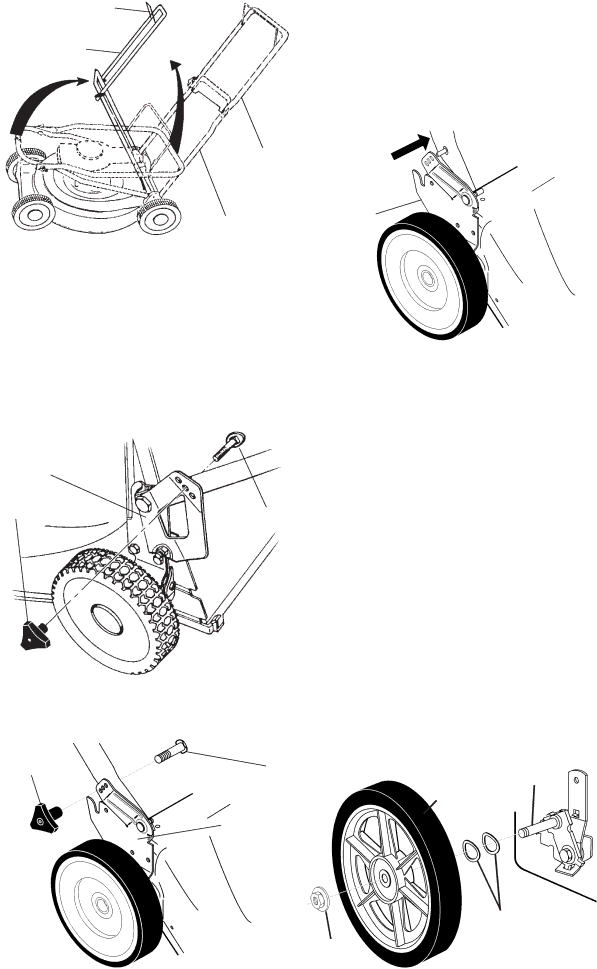
INSTALL REAR WHEELS (HIGH WHEEL MOWERS ONLY)
Some high wheel models require washers which will be provided in a parts bag. If provid- ed, install washers on the axle first as shown.
•Install one (1) rear wheel on the axle of rear wheel adjuster.
•Install
•Repeat procedure for other rear wheel.
Wheel Axle assembly
Wave
Washers
Flanged
5locknut