Accton Technology ES4524M-POE manual Fiber Optic SFP Devices, Wiring Closet Connections

Page 39

Fiber Optic SFP Devices 4

1.Attach one end of a patch cable to an available port on the switch, and the other end to the patch panel.

2.If not already in place, attach one end of a cable segment to the back of the patch panel where the punch-down block is located, and the other end to a modular wall outlet.

3.Label the cables to simplify future troubleshooting. See “Cable Labeling and Connection Records” on page
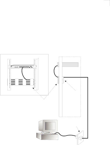
 4-6.

Network Switch

Patch Panel

Equipment Rack (side view)

Punch-Down Block

Wall

Figure 4-2 Wiring Closet Connections

Fiber Optic SFP Devices

An optional Gigabit SFP transceiver (1000BASE-SX, 1000BASE-LX or 1000BASE-ZX) can be used for a backbone connection between switches, or for connecting to a high-speed server.

Each single-mode fiber port requires 9/125 micron single-mode fiber optic cable with an LC connector at both ends. Each multimode fiber optic port requires 50/125 or 62.5/125 micron multimode fiber optic cabling with an LC connector at both ends.

4-3

Image 39
Contents Powered by Accton Page L2/4 Gigabit Ethernet Switch ES4524M-PoE E122007-LP-R01 149100037400A Compliances and Safety Warnings Warnhinweis Faseroptikanschlüsse Optische Sicherheit Safety ComplianceVii France et Pérou uniquement ViiiEnd of Product Life Span Manufacturing MaterialsDocumentation Page About This Guide Xii Contents Making Network Connections ContentsIndex Xvi Tables Figures Switch Architecture About the ES4524M-PoEOverview 10/100/1000BASE-T Ports Power-over-Ethernet CapabilityDescription of Hardware Network Management OptionsPort and System Status LEDs SFP SlotsFeatures and Benefits Power Supply SocketConnectivity Expandability PerformanceManagement About the ES4524M-PoE Collapsed Backbone Introduction to SwitchingNetwork Planning Application ExamplesNetwork Planning Network Aggregation PlanMaking Vlan Connections Remote Connections with Fiber CableMaking Vlan Connections Application NotesInstalling the Switch Selecting a SiteEthernet Cabling Equipment Checklist Package ContentsOptional Rack-Mounting Equipment Mounting Rack MountingMounting Desktop or Shelf Mounting Installing the Switch in a RackInserting an SFP Transceiver into a Slot Installing an SFP TransceiverConnecting to the Console Port Connecting to a Power SourceDTE Port Wiring Map for Serial CableInstalling the Switch Twisted-Pair Devices Connecting Network DevicesPower-over-Ethernet Connections Making Network ConnectionsConnecting to PCs, Servers, Hubs and Switches Network Wiring ConnectionsMaking Network Connections Fiber Optic SFP Devices Wiring Closet ConnectionsMaking Connections to SFP Transceivers Connectivity Rules 1000BASE-T Cable RequirementsMbps Gigabit Ethernet Collision Domain Cable Labeling and Connection Records Mbps Fast Ethernet Collision DomainMbps Ethernet Collision Domain Installation Appendix a TroubleshootingDiagnosing Switch Indicators Power and Cooling ProblemsTroubleshooting In-Band AccessAppendix B Cables Twisted-Pair Cable and Pin Assignments10BASE-T/100BASE-TX Pin Assignments Cables Straight-Through WiringCrossover Wiring 1000BASE-T Pin AssignmentsTwisted-Pair Cable and Pin Assignments B Cable Testing for Existing Category 5 Cable Adjusting Existing Category 5 Cabling to Run 1000BASE-TFiber Standards Physical Characteristics Appendix C SpecificationsStandards Switch FeaturesManagement Features SpecificationsWarranty CompliancesCompliances C Specifications Glossary-1 GlossaryGlossary-2 GlossaryGlossary-3 Ieee 802.3zGlossary-4 TIAIndex-1 IndexIndex-2 IndexPage ES4524M-PoE E122007-LP-R01 149100037400A