Dell E6330 owner manual Installing the Lvds and Camera Cable

Page 54

Installing the LVDS and Camera Cable

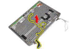
1.Route the LVDS and camera cable on the display assembly.

2.Fix the adhesive the tape to secure the cable.

3.Connect the LVDS and camera cable to the camera and microphone module.

4.Install:

a)display hinge walls

b)power LED board

c)display panel

d)display bezel

e)display assembly

f)display hinge covers

g)media board

h)palmrest

i)bluetooth module

j)keyboard

k)keyboard trim

l)base cover

m)optical drive

n)hard drive

o)battery

p)ExpressCard

q)SD card

5.Follow the procedures in After Working Inside Your Computer.

54

Image 54
Contents Regulatory Model P19S Regulatory Type P19S001 Dell Inc Contents Docking Port Information System Setup Technical Specifications Contacting Dell Page Working on Your Computer Before Working Inside Your ComputerTurning Off Your Computer After Working Inside Your ComputerPage Page Installing the Secure Digital SD Card Recommended ToolsRemoving the Secure Digital SD Card Installing the ExpressCard Removing the BatteryRemoving the ExpressCard Installing the Battery Removing the Subscriber Identity Module SIM cardInstalling the SIM Card Removing the Hard DriveInstalling the Hard Drive Removing the Optical Drive Installing the Optical Drive Installing the Base Cover Removing the Base CoverRemoving the Keyboard Trim Installing the Keyboard Trim Removing the KeyboardPage Installing the Keyboard Removing the Wireless Local Area Network Wlan Card Installing the Wlan CardRemoving the Bluetooth Module Installing the Bluetooth Module Installing the Memory Removing the MemoryRemoving the Coin-Cell Battery Installing the Coin-Cell BatteryRemoving the Palmrest Page Installing the Palmrest Removing the Media Board Installing the Media Board Removing the ExpressCard CageInstalling the ExpressCard Cage Removing the Speakers Installing the Speakers Removing the Display-Hinge CoversInstalling the Display Hinge Covers Removing the Display AssemblyPage Page Installing the Display Assembly Removing the System BoardPage Installing the System Board Removing the Heat Sink Installing the Heat Sink Removing the Power Connector PortInstalling the Power-Connector Port Removing the Input/Output I/O Board Installing the I/O Board Removing the Display BezelInstalling the Display Bezel Removing the Display PanelInstalling the Display Panel Removing the Camera and Microphone ModuleInstalling the Camera and Microphone Module Removing the LED Board Installing the LED Board Removing the Display-Hinge WallsPage Installing the Display-Hinge Walls Removing the Display Hinges Installing the Display Hinges Removing the Lvds and Camera CablePage Installing the Lvds and Camera Cable Docking Port Information Page Boot Sequence Navigation KeysKeys Navigation System Setup Options Serial Port Option DescriptionParallel Port Sata OperationStealth Mode Control USB ConfigurationUSB PowerShare Keyboard IlluminationInternal HDD-0 Password Admin PasswordSystem Password Strong PasswordDefault Setting Enable Intel SpeedStep Orom Keyboard AccessAdmin Setup Lockout Default Setting Enable Intel TurboBoostOption Description AC Behavior Wireless Radio ControlPrimary Battery Configuration Auto On TimeNumlock Enable Battery Slice ConfigurationTouchpad/PS-2 Mouse Default Setting Keyboard ErrorsUpdating the Bios Password that you must enter to log on to your system System and Setup PasswordPassword Type Description Setup passwordPress Y to save the changes. The computer reboots Page Enhanced Pre-Boot System Assessment ePSA Diagnostics Device Status LightsTemporary battery failure with AC adapter present Battery Status LightsStorage LED Power LED Wireless LED Fault Description Light Your laptopProcessor MemoryAudio Communications Ports and ConnectorsVideo Contactless Smart CardKeyboard TouchpadBattery AC AdapterPhysical EnvironmentalPage Contacting Dell Visit support.dell.com