17-INCH specifications
The Apple 17-inch model has garnered attention for its impressive balance of performance and portability, making it a popular choice among professionals and creative users alike. Boasting a sleek design, it combines cutting-edge technologies with user-friendly features that enhance productivity and entertainment experiences.At the heart of the 17-inch display is Apple's Retina technology, which provides stunning visual clarity and vibrant colors. With a resolution that surpasses traditional screens, users can expect crisp text and detailed images, making it an ideal choice for graphic designers, video editors, and anyone who values high-quality visuals. The large screen size creates an immersive experience, especially useful for multitasking, viewing spreadsheets side by side, or editing documents side by side.
Powered by Apple’s latest custom silicon, the 17-inch model delivers remarkable performance. The optimizations in the chip architecture enhance not only processing speeds but also energy efficiency, allowing users to accomplish more without compromising battery life. These advancements in chip technology together with integrated graphics offer smooth performance during intensive tasks such as rendering high-definition graphics or playing demanding games.
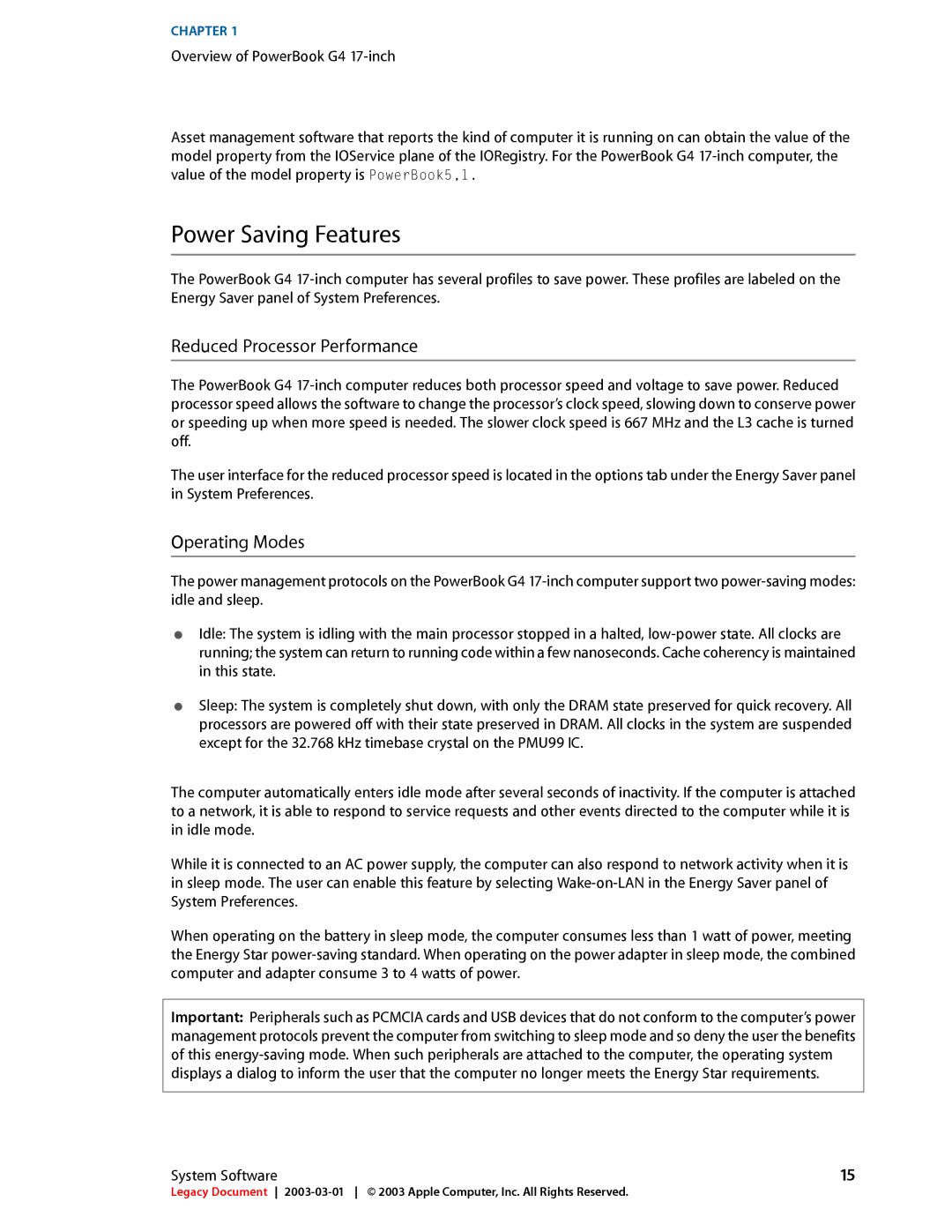
The laptop also comes equipped with a robust battery system designed to keep users productive for extended periods. Users can expect several hours of usage on a single charge, ensuring that they can work or enjoy media without the constant need to recharge. Furthermore, fast-charging capabilities minimize downtime, making it convenient for on-the-go professionals.
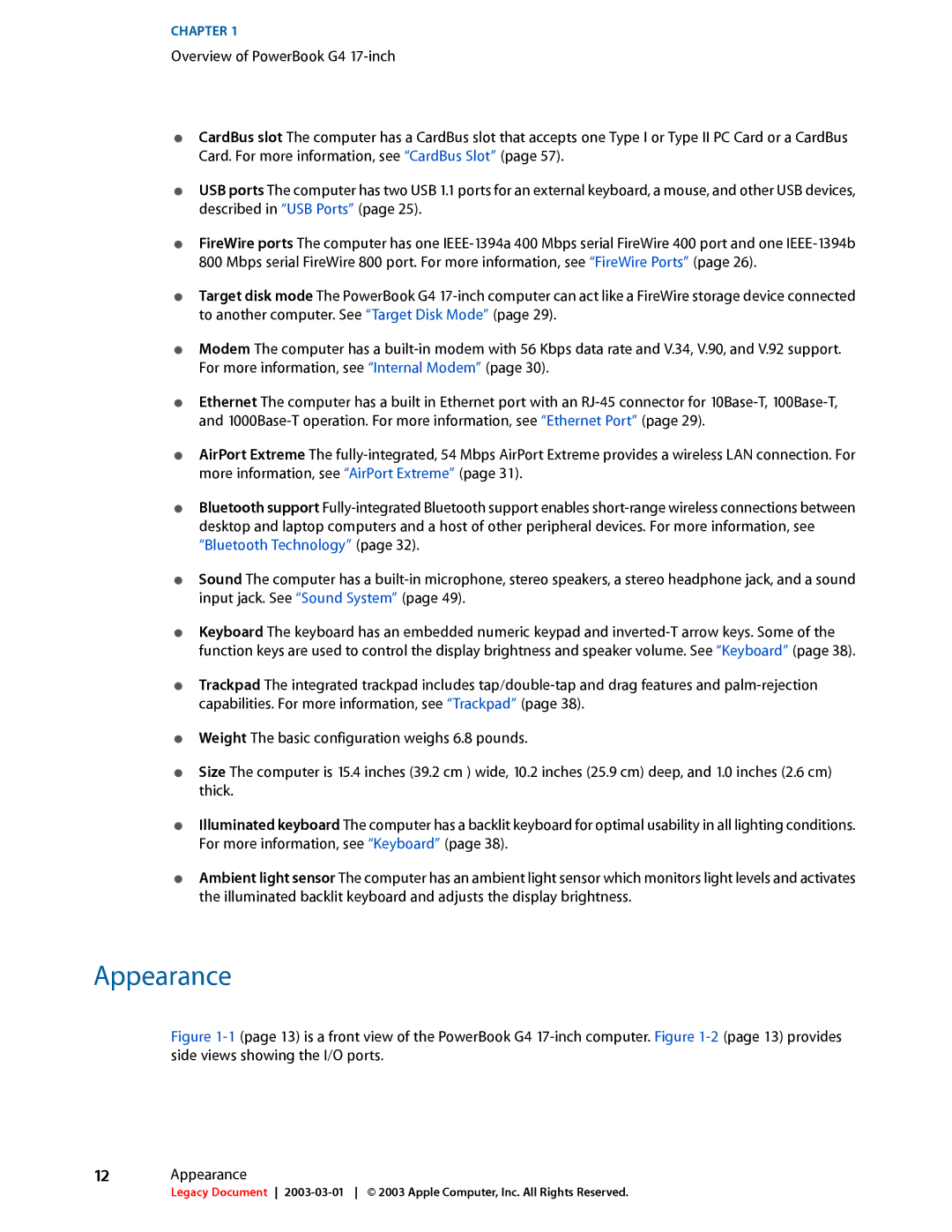
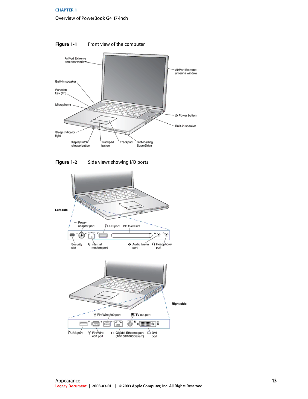
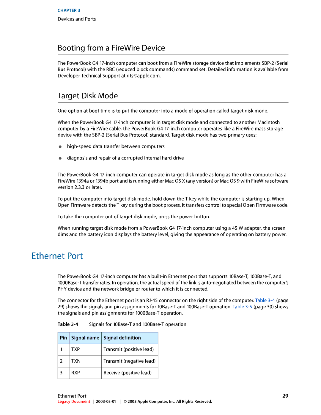
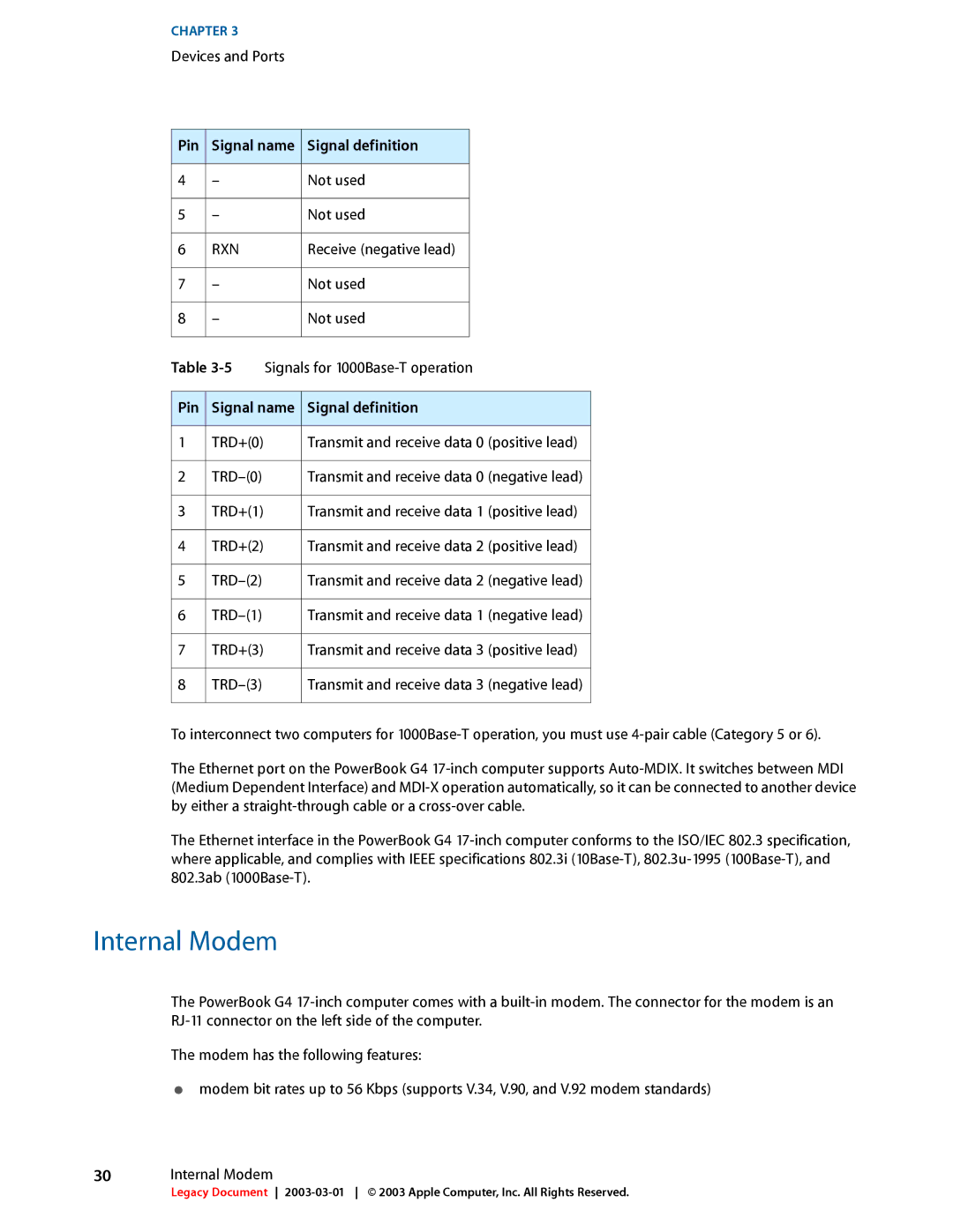
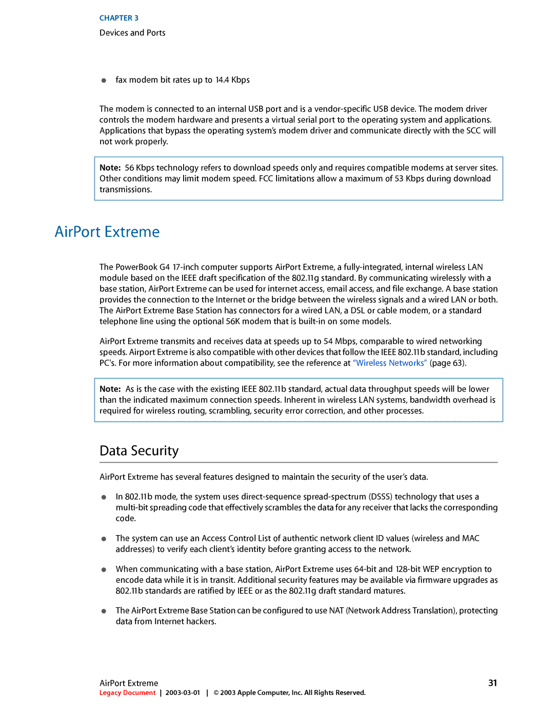
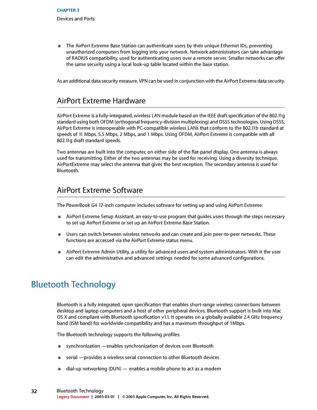
In terms of connectivity, the 17-inch model offers multiple Thunderbolt and USB-C ports, allowing for quick data transfer and connecting a variety of external devices. This versatility is essential for professionals who may need to hook up to external monitors or utilize peripherals for enhanced functionality.
The built-in audio system features high-fidelity speakers, delivering an outstanding audio experience for music, movies, and video conferencing. The integration of advanced microphones further enhances clarity during calls, making communication seamless.
Overall, the Apple 17-inch laptop stands out as a powerful tool designed for those who demand performance, quality, and flexibility in their devices. With its blend of stunning visuals, powerful processing capabilities, and user-centric features, it remains a strong contender in the market for those seeking a reliable and stylish computing solution.
