Mitsubishi Electronics WS-65315A, WS-55315, WS-48315 manual Side Panel Input/Output for WT-42315

Page 11

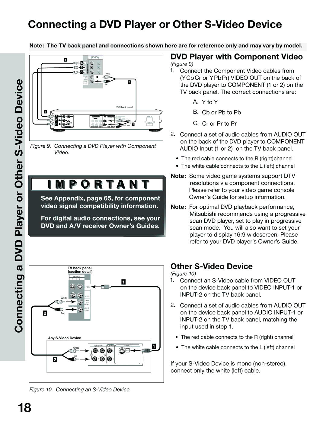
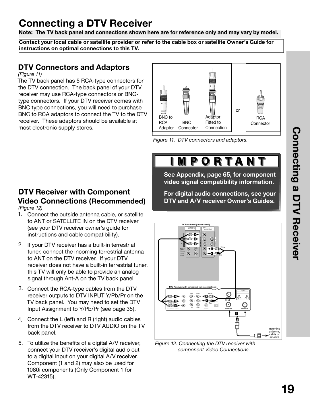
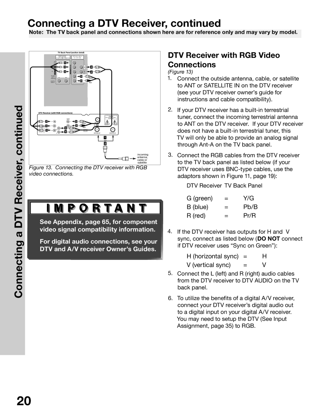
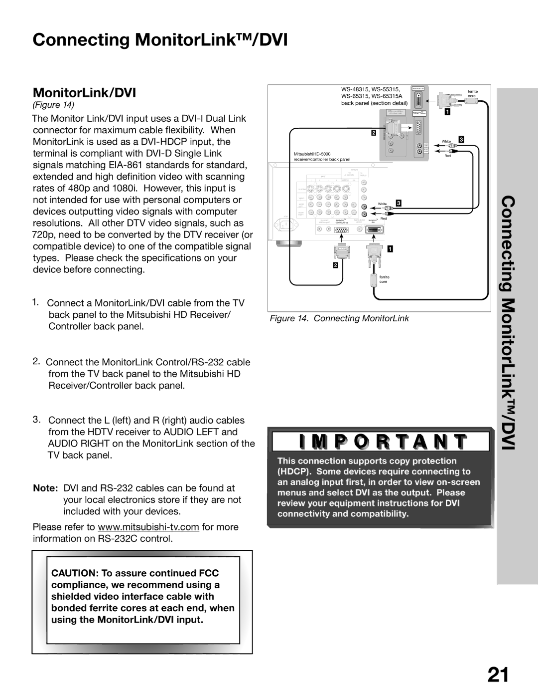
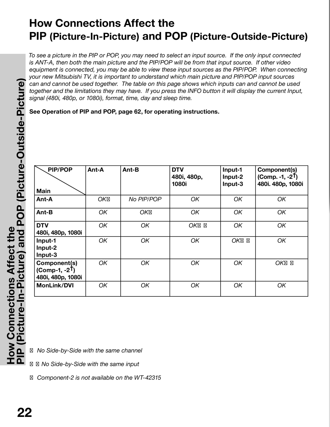
Back Panel Input/Output for WS-48315, WS-55315, WS-65315 &WS-65315A

Side Panel Input/Output for WT-42315

6

WS-48315, WS-55315, WS-65315, WS-65315A

2


3

Back Panel

4

5


COMPONENT

DTV(YPbPr/ GBRHV)


480 i / 480P/ 1080i

480i / 480P /1080i


1

2

MONITOR


I N P U T


OUT

1

2


Y


Y


G


MONITORLINKTM/DVI

MONITORLINKTM CONTROL RS-232C

�������� ���� �����

������� ����� �����

�������

������

����� �

7

����� �


S-VIDEO


Pb

H


��� ����

���� ���������� �����


Pb

B


P r

V


���������


Back/Side


V IDEO

P r


X-RAY PRECAUTION: THIS PRODUCT INCLUDES CRITICAL MECHANICAL AND


����


R


�����������������


AUDIO-

AUDIO -


LEFT /

L EFT /


AUDIO-


(MONO)


LEFT/

���


(MONO)


AUDIO-

AUDIO -


AUDIO-

�����������������


RIGHT

RIGHT


RIGHT


SERVICE WARNING


CAUTION: TO MEASURE SECOND ANODE VOLTAGE USE A HIGH VOLTAGE METER


LOOP

CONNECTED FROM ANODE LEAD TO CHASSIS ONLY. DISCHARGE HIGH VOLTAGE TO CHASSIS


ONLY, NOT TO EXTERNAL GROUND.


1

ANT - A

OUT ANT- B

WARNING: HANDLE WITH CARE HIGH VACUUM PICTURE TUBE IS DANGEROUS TO


HANDLE. REFER SERVICING TO QUALIFIED SERVICE PERSONNEL. REPLACE WITH A TUBE


�����������

��


OF THE SAME TYPE NUMBER FOR CONTINUED SAFETY.


ELECTRICAL PARTS WHICH ARE ESSENTIAL FOR X-RADIATION SAFETY. FOR CONTINUED


�������������

Panel


SAFETY REPLACE CRITICAL COMPONENTS INDICATED IN THE SERVICE MANUAL ONLY WITH


EXACT REPLACEMENT PARTS GIVEN IN THE PARTS LIST. REFER TO SERVICE MANUAL FOR


���������������


OPERATING HIGH VOLTAGE AT MINIMUM BRIGHTNESS, MEASUREMENT PROCEDURES AND


PROPER SERVICE ADJUSTMENTS.


�� � � �

��� �

�� �� �


���

Input/Output

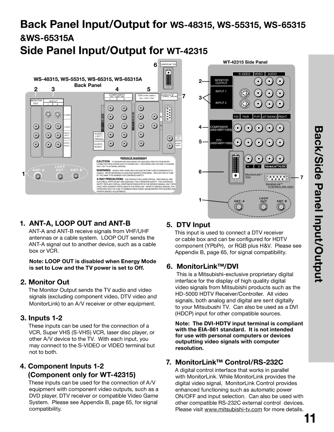
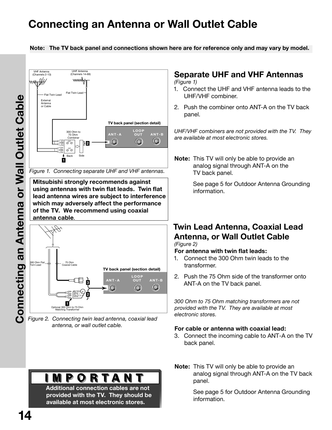
1. ANT-A, LOOP OUT and ANT-B


5. DTV Input


ANT-A and ANT-B receive signals from VHF/UHF


This input is used to connect a DTV receiver


antennas or a cable system. LOOP OUT sends the


or cable box and can be configured for HDTV


ANT-A signal out to another device, such as a cable


component (YPbPr), or RGB plus H&V. Please see


box or VCR.


Appendix B, page 65, for signal compatibility.


Note: LOOP OUT is disabled when Energy Mode

6. MonitorLink™/DVI


is set to Low and the TV power is set to Off.


This is a Mitsubishi-exclusive proprietary digital


2. Monitor Out


interface for the display of high quality digital


The Monitor Output sends the TV audio and video


video signals from Mitsubishi products such as the


HD-5000 HDTV Receiver/Controller. All video


signals (excluding component video, DTV video and


signals, both analog and digital are sent digitally


MonitorLink) to an A/V receiver or other equipment.


to your Mitsubushi TV. Can also be used as a DVI


3. Inputs 1-2


(HDCP) input for other compatible sources.


Note: The DVI-HDTV input terminal is compliant


These inputs can be used for the connection of a


with the EIA-861 standard. It is not intended


VCR, Super VHS (S-VHS) VCR, laser disc player, or


for use with personal computers or devices


other A/V device to the TV. With each input, you


outputting video signals with computer


may connect to the S-VIDEO or VIDEO terminal but


resolution.


not to both.


4. Component Inputs 1-2


7. MonitorLink™ Control/RS-232C


A digital control interface that works in parallel


(Component only for WT-42315)


with MonitorLink. While MonitorLink provides the


These inputs can be used for the connection of A/V


digital video signal, MonitorLink Control provides


equipment with component video outputs, such as a


enhanced functioning such as automatic power


DVD player, DTV receiver or compatible Video Game


ON/OFF and input selection. Can also be used with


System. Please see Appendix B, page 65, for signal


other compatible RS-232C external control devices.


compatibility.


Please visit www.mitsubishi-tv.com for more details.11


Image 11
Contents Owner’s Guide Page Contents ContentsImportant Safeguards Safeguards Important Notes Television Overview Chapter OUR Promise Thank You for Your PurchaseUnpacking Special FeaturesYour New TV /Special Features Unpacking Your New TVFormat TimerReset Front Control PanelWS-48315, WS-55315, WS-65315, WS-65315A Back Panel Side Panel Input/Output for WT-42315Important Notes Connections Connecting a DTV Receiver Connecting MonitorLink/DVIFor antenna with twin flat leads Connecting an Antenna or Wall Outlet CableOutlet Cable Separate UHF and VHF AntennasCable Box Connecting an Antenna to a Cable Box or VCRConnecting an To a Cable Box or VCRConnect three coaxial cables as follows Composite Video with Audio or S-Video with AudioRecommendedReceiver Connecting an Audio ReceiverStereo Audio System DVD Player Connecting a DVD Player or Other S-Video DeviceConnecting Or OtherDTV Receiver with Component Video Connections Recommended Connecting a DTV ReceiverDTV Connectors and Adaptors DTV ReceiverGreen Blue Pb/B Red Pr/R MonitorLink/DVI Connecting MonitorLink/DVIMonitorLink/DVI Ant-A Ant-B How Connections AffectPIP Picture-In-Picture and POP Picture-Outside-Picture Remote Control Functions Overview Remote Control Functions Overview of the TV Layer ButtonsOperation Remote Control Functions Care and OperationOperating the Remote Control For Best Results from the Remote ControlChannel Selection Sleep TimerSetting the Sleep Timer Canceling the Sleep TimerUse Use of the Remote Control with Other A/V ProductsRemote Control with Other A/V Products Use of the Remote Control with Other A/V Products Activating the PIP and POP Remote Control Functions Special FunctionsOperation of PIP and POP Important Notes Menu Screen Operations Menu Menu SystemSystem Channel Edit Menu Setup MenuMain Menu Screens Overview Captions MenuChip Lock Menu Advanced Features MenuAUDIO/VIDEO Settings Menu Input Assignment Menu Memorize ChannelsMemorize Menu Set Day Setup Menu Manually Setting the ClockClock Setting Manual Daylight Savings Time Setup Menu Automatically Setting the ClockClock Setting Auto Time ZoneFront Button Lock for WT-42315 Setup Menu Language, Front Button Lock WT-42315Language WS-48315, WS-55315, WS-65315 Setup Menu Energy ModeWS-65315A Energy Mode Captions Menu Overview CC Background Captions Menu Closed Captions, Background ColorClosed Captions Channel Channel Edit Menu Antenna, Channel SelectionAntenna Memory Channel Edit Menu Memory, Name SelectionChannel Edit Menu Memory, Name SelectionUsing The Remote Control Channel Edit Menu Using SQV Super Quick ViewMenu Using SQV Using The Menu ScreenMenu Overview Chip Signal InformationChip Lock Menu Overview Entering the Passcode Chip Menu Setting Up and Using V-Chip Lock PasscodeSetting Up the V-CHIP Lock Passcode Lock by Time, Lock Time, and Unlock Time Allowing or Blocking by RatingsChip Start Time and V-CHIP Stop Time Selecting V-Chip Rating Menu Lock by TimeFront Button Lock Chip Start Time Chip Stop Time Allowing or Blocking Ratings, Lock by TimePerfectColor Reset ColorColor Balance Menu Auto Color CorrectionSet Time Advanced Features Menu TIMER, Timer Menu, and Set TimeTimer menu Input Advanced Features Menu Set Day, Input, and ChannelAdvanced Convergence Advanced Features Menu ConvergenceConvergence Menu Convergence ScreenBlack Enhancement Video MuteSettings Menu Overview AUDIO/VIDEO Settings Menu OverviewAudio Settings AUDIO/VIDEO Setting Descriptions AudioVideo Settings AUDIO/VIDEO Setting Descriptions VideoThis page intentionally blank Available On-Screen Format Sizes Operation of PIP and POP PIP/POP OperationsAvailable On-Screen Format Sizes Widescreen Picture 480i/480p Operation of PIP and POP Bypassing the V-Chip Lock Appendix a Bypassing V-Chip LockAppendix a Bypassing the V-Chip Lock This page intentionally blank Appendix B High Definition Input Connection Compatibility Cable Box DVD Players Appendix C Remote Control Programming CodesReceivers DBS/DTV Satellite Receivers VCRsGeneral Cleaning Warnings Appendix D Cleaning and ServiceCleaning ServiceInstallation Page Stand Requirement Terminal Cover Ventilation for Model WT-42315Terminal Cover Ventilation for Model WT-42315Index IndexLock by Time for Problem Possible Solution TroubleshootingPage Mitsubishi Digital Electronics America, Inc 871D404B10