Siemens Mux_guide_v06 manual Serial Interface Customer GSM engine, At+Cmux

Page 23

Multiplexer User's Guide

Confidential / Released

s

mobile


Serial


interface


Customer


GSM engine


µC


µC


Closed Down


Closed Down


RequestStartUp

IndicationStartUp

Start Up

"AT+CMUX"


ConfirmStartUp

ResponseStartUp


Disconnected


Disconnected


RequestSABM

IndicationSABM

DLC Establishment, DLC not created


ConfirmDM

ResponseDM


Disconnected


Disconnected


RequestSABM

IndicationSABM

DLC Establishment,

DLC created


ConfirmUA

ResponseUA


Connected


Connected


RequestUIH

IndicationUIH


Connected


Connected

Information

Transfer


RequestUIH


IndicationUIH


Connected


Connected


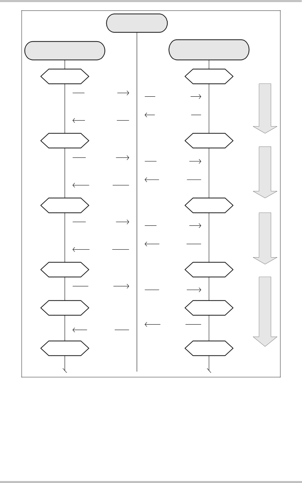
Figure 5: MPI – Startup, DLC establishment and information transfer

Mux_guide_v06

Page 23 of 36

30.06.2004

Image 23
Contents Siemens Cellular Engines Version DocID Muxguidev06Muxguidev06 Document Name Multiplexer Users GuideMultiplexer Users Guide June 30Contents Multiplexer protocol version control TablesDocument history Chapter What is newIntroduction References Supported products and related documentsAbbreviation Description Term and abbreviationsProduct concept and architecture Multiplexer protocol an overviewVirtual channels and AT commands Restrictions CharacteristicsIntegrating multiplexer into the customer application Basic requirementsFunctions without channel dependencies Timing conditions RTS/CTS on the physical channels Multiplexer control and signaling linesFlow control Logical flow controlCOM M COM N COM P RTS/CTS RTS/CTS on the logical channelsEscape sequence Power savingBandwidth of logical channels Data link layer Structure of the multiplexer protocolIntroduction of the multiplexer protocol Address field Flag sequenceFrame Type Control fieldBit Length indicatorInformation field Frame checking sequence field FCSState diagrams Relationship between the customer µC and the GSM engine µC AT+CMUX Serial Interface Customer GSM engineCustomer µC Serial interfaceResponder CustomerEngine GSM engineType field Close-down procedureDLC release Multiplexer control channelLength field Test command TestMultiplexer close down CLD Modem status command MSC Break signal optional Bit Not supported Value octet Length=1 Bit Power saving control PSCCommands Bit Description Type BitNo Value octet Length=0 Non-supported command response NSCValue octet Bit Command Type Non-supported commandAT+CMUX Customer GSM engine µCIntroduction Multiplexer protocol version controlMultiplexer protocol versions Modem status command MSCSignals Break Signals Octet Optional Command Bit Signals BitImplementing version control TroubleshootingExample of TestCommand message Coding of TestCommand message