BASSBASE 400 - MANUAL
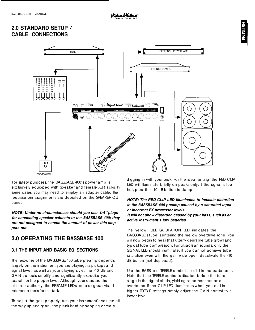
2.0STANDARD SETUP / CABLE CONNECTIONS
TUNER
FOOTSWITCH
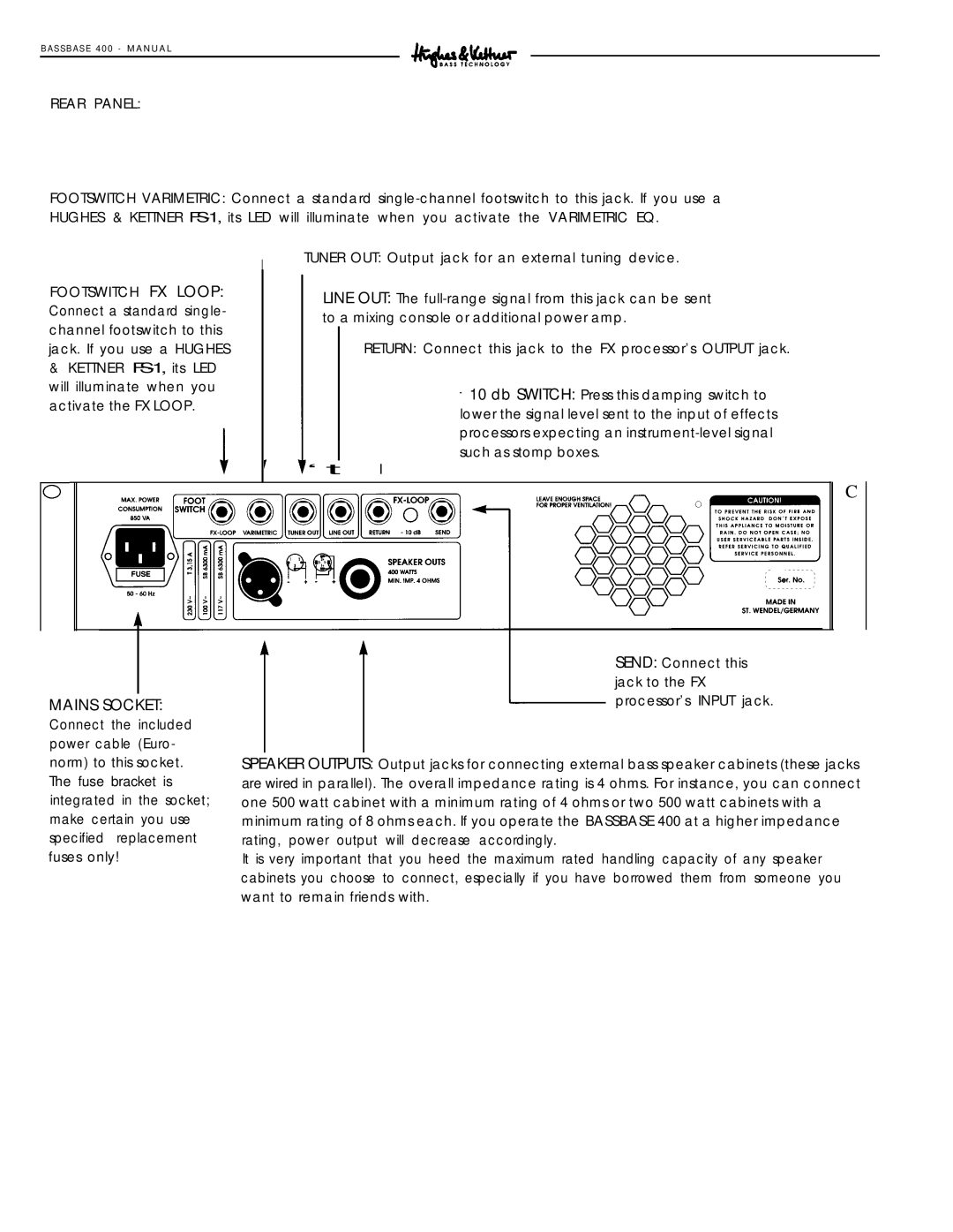
For safety purposes, the BASSBASE 400’s power amp is exclusively equipped with Speaker and female XLR jacks. In some cases, you may need to employ an adapter cable. The requisite pin assignments are depicted on the SPEAKER OUT panel.
NOTE: Under no circumstances should you use 1/4" plugs for connecting speaker cabinets to the BASSBASE 400; they are not designed to handle the amount of power this amp puts out.
3.0OPERATING THE BASSBASE 400
3.1THE INPUT AND BASIC EQ SECTIONS
The response of the BASSBASE 400 tube preamp depends largely on the instrument you are playing, its pickups and signal level, as well as your playing style. The
To adjust the gain properly, turn your instrument’s volume all the way up and spank the plank hard by slapping or really
EXTERNAL POWER AMP
digging in with your pick. For the ideal setting, the RED CLIP LED will illuminate briefly on peaks only. If the signal is too hot, press the
NOTE: The RED CLIP LED illuminates to indicate distortion in the BASSBASE 400 preamp caused by a saturated input or incorrect FX processor levels.
It will not show distortion caused by your bass, such as an active instrument’s low batteries.
The yellow TUBE SATURATION LED indicates the BASSBASE's tube is entering the mellow overdrive zone. You will now begin to hear that utterly desirable tube growl and typical tube compression. For ultraclean sounds, only the SIGNAL LED should illuminate. If you cannot achieve tube saturation even with the gain wide open, deactivate the
Use the BASS and TREBLE controls to dial in the basic tone. Note that the TREBLE control is situated before the tube stage in the signal chain, yielding smoother harmonic overtones. If the CLIP LED illuminates when you dial in higher TREBLE settings, simply adjust the GAIN control to a lower level.
7

