REAR PANEL
2831
POWER |
|
|
|
|
|
|
|
| AC100V 50 / 60Hz 20W | ||
|
|
|
|
|
|
| MADE IN CHINA | SERIAL NO. |
|
| |
|
|
|
|
|
|
|
|
|
| ||
ON | OUTPUT |
|
| EFFECT |
|
| PGM 2 |
| SUB | PGM 1 |
|
R | MASTER OUT 1 | L | R | SEND | L | R | LINE 6 | L | R | LINE 2 | L |
| OFF |
|
| R |
| L |
|
|
|
| LINE 3 | ||
|
|
| LINE 5 |
|
| LINE 1 |
| R | L |
|
|
|
|
| MASTER OUT 2 |
| PHONO 3 |
| PHONO 2 | PHONO 1 |
|
|
| RETURN |
|
|
|
|
|
|
|
| GND | GND |
29 | 30 | 32 | 33 | 35 |
| 34 |
○28 POWER SWITCH
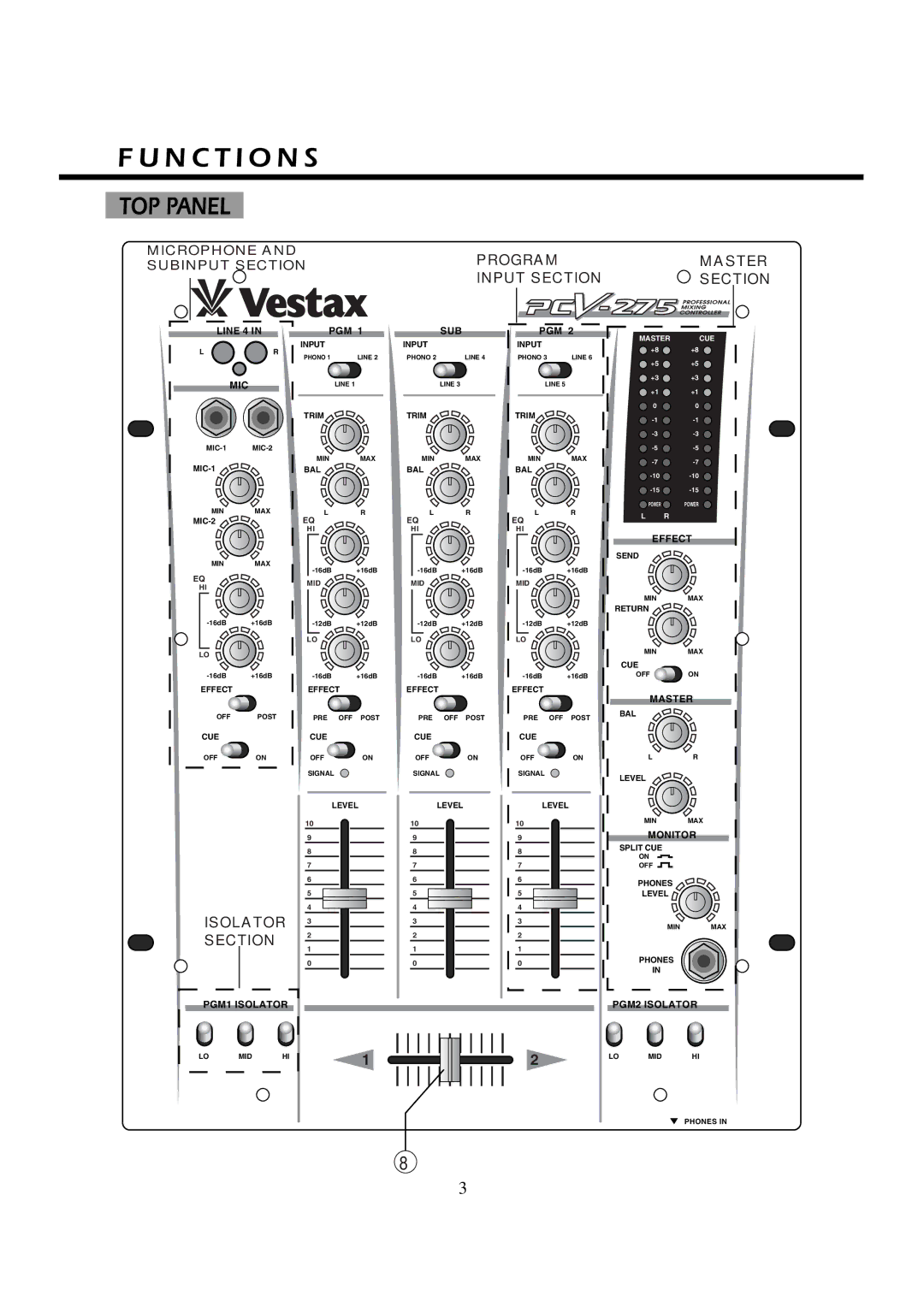
The first LED of MASTER OUT LEVEL METER that is located on the top panel is lit when on.
○29 AC POWER CABLE
○30 OUTPUT JACK(1/4inch PHONE JACK, RCA
PIN JACK)
Connect to the input of power amplifier.
○31 EFFECT SEND JACK
Connect the SEND jacks to the input of an external effector unit(Delay,Reverb etc)
○32 EFFECT RETURN JACK
Connect the RETURN jacks to the output of the effector.
○33 PHONO INPUT JACK
Input jack for PGM1,PGM2 and SUB channel turntables.
Connect turntables equipped with the MM pick up cartridge only.
○34 LINE INPUT JACK
Input connectors for the line level equipment such as CD players, tape decks, DATs, MDs.
○35 GROUND TERMINAL
Connect this terminal to the ground lead of the turntable. This helps to reduce noise and hum.
SPECIFICATIONS
●NOMINAL INPUT LEVEL/IMPEDANCE
PHONO |
| -42dB/470k | |
LINE |
|
| -10dB/47k |
MIC |
|
| -42dB/3.3k |
EFFECT | RCV | -10dB/47k | |
●RATED OUTPUT LEVEL/IMPEDANCE | |||
LINE | OUT | -4dB/10KΩ | |
REC | OUT | -10dB/10kΩ | |
EFFECT | SEND | -10dB/10kΩ | |
●FREQUENCY RESPONSE 20Hz~20kHz (+0,-3dB)
●S/N RATIO -80dB
●DIMENSION ( WXHXD ) 290mmX94mmX380mm
●WEIGHT 5kg
May.2001
Vestax Corporation


