Multiquip WM120PM, WM120SM manual WM-120P/S Towing, Step

Page 13

NOTE

Before towing, check with local and state laws for proper compliance.

The tow bar and chain must be properly attached to the mixer and towing vehicle prior to towing. Refer to the following installation instruction:

Step 1.

Insert the Draw Bar into the main frame. Secure, utilizing the 3/4" bolt (grade 5) and nylock nut.Tighten to 100 foot pounds.
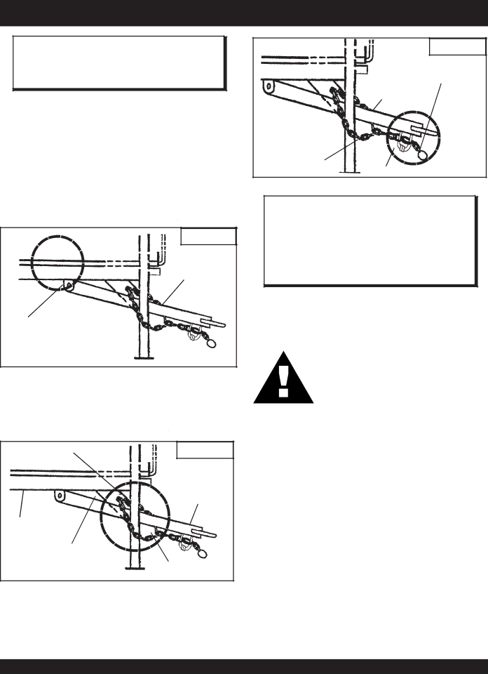
STEP 1

DRAW BAR

BOLT & NUT

Step 2.

Install the chain through the hole located between the frame gusset and frame angle. Loop the chain together and place under the Draw Bar.Secure with connector link.

INSERT CHAIN THROUGH

STEP 2

THE HOLE


DRAW BAR

FRAME ANGLE


FRAME GUSSET

CONNECTOR LINK

Step 3.

Extend the chain along the length of the Draw Bar, remove excess chain (slack) and secure to bottom connector link. Secure the chain to the towing vehicle, using the connector link.

WM-120P/S — TOWING

STEP 3

VEHICLE

CONNECTOR LINK

DRAW BAR

REMOVE EXCESS

CHAIN (SLACK)

BOTTOM CONNECTOR LINK

NOTE

It is critical that the length of the chain be properly adjusted, to prevent the Draw Bar and the front mixer stand from dropping to the ground (contact) in the event the Draw Bar becomes disconnected from the towing vehicle.

If a new safety chain is required use P/N 13363. For a new connector link use P/N 01004.

CAUTION:

Check the following before towing:

BALL HITCH COUPLER

1.Check vehicle hitch, ball, and coupler for signs of wear or damage. Replace any parts that are worn or damaged before towing.

2.Use only the 2" ball diameter as indicated on your coupler. Use of any other ball diameter will create an extremely dangerous condition which can result in separation of the coupler and ball or ball failure.

3.Be sure the coupler is secured to the hitch ball and the lock lever is down tight and locked.

Recheck tightness again after towing about 50 miles.

4.Check that trailer safety chains are properly connected.

WM120PM/SM — OPERATION AND PARTS MANUAL — REV. #7 (09/15/11) — PAGE 13

Image 13
Contents WM120PM Series Proposition 65WARNING SILICOSIS/RESPIRATORYWARNINGS Engines Ordering parts has never been easier Parts Ordering ProceduresOperation and Safety Decals Safety InstructionsRules for Safe Operation General SafetyEmergencies Rules for Safe OperationWM120PM WM120SM WM120P/S SpecificationsWM120P/S General Information Mixer WM-120P/S ControlsElectric Motor WM-120P/S Electric MotorElectric Motor Connection Step WM-120P/S TowingPaddle Blade Adjustment, Polyethylene Drum WM-120P/S Paddle Blade AdjustmentWM-120P/S Paddle Blade Adjustment WM-120P/S Initial START-UP Mixing WM-120P/S Initial START-UPStarting the Electric Motor WM-120P/S Maintenance Clutch Adjustment Mechanical 12 CF Mixer WM-120P/S MaintenanceEngine Troubleshooting Symptom Possible Problem Solution WM-120P/S -TROUBLESHOOTING EngineWM-120P/S -TROUBLESHOOTING ENGINE/MIXER Xxxxx only Not Used on WM-120P/S- Explanation of Code in Remarks ColumnWM-120PS 1 to 3 Units WM-120PS 5 to 10 Units WM-120P/S- Suggested Spare PartsWM-120P/S Engine Side Paddle Assy Paddle ARM Center Engine Side Paddle ARM Engine SideFlat Washer 5/16 END BACK-UP BladeWM-120P/S -TOW Side Paddle Assy Center Paddle U-BOLT Paddle ARM Center TOW SideLocl Washer 1/2 Included in Blade KitsWM-120P/S Paddle Shaft Assy RING, Snap Seal Bearing 1-1/2 IDSPACER, Snap Ring BEARING, BallWM-120P/S Polyethylene Drum Assy CAP, Grease Zerk WASHER, FLAT, 3/8 SAEWASHER, FLAT, 1/2 USS GRATE, 120 Stationary W/AWM-120P/S Steel Drum Assy SHIM, Bearing Brkt TUB, SteelDump Lever BAR, Grill OpeningWM-120P/S CAB Assy CAB DOOR, Complete Assy WM-120P/S FRAME,WHEEL,TIRE and HUB Assy Transmission Support BAR Safety Chain AssyFlat Washer 1/2 Frame W/AWM-120P/S Name Plate and Decals PLATE, Serial no Decal CautionDCLWM120PS KIT, Decal Includes Items W WM-120P/S -WISCONSIN Engine Assy Engine Kill Ground Wire Kill SwitchEnginekill Wire Connecting LinkWM-120P/S Honda Engine Assy Wire Splice Engine Kill Wire11HP Honda Engine Engine ShimWM-120P/S Electric Motor Assy HP 3 Phase Elect Motor HP 1 Phase Elect MotorMotor Starter 1 Phase Motor Starter 3 PhaseWM-120P/S -TRANSMISSION Assy Shifter Shaft Main Transmission HousingClutch Yoke Lock Washer 1/4Terms and Conditions of Sale Parts WM120PM/SM Operation and Parts Manual REV. #7 09/15/11 HERE’S HOW to GET Help