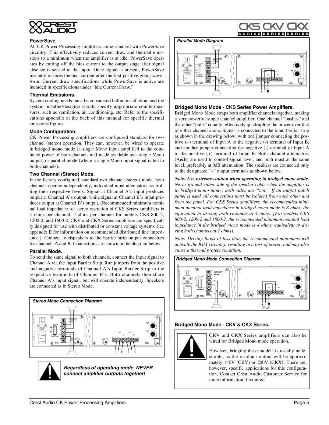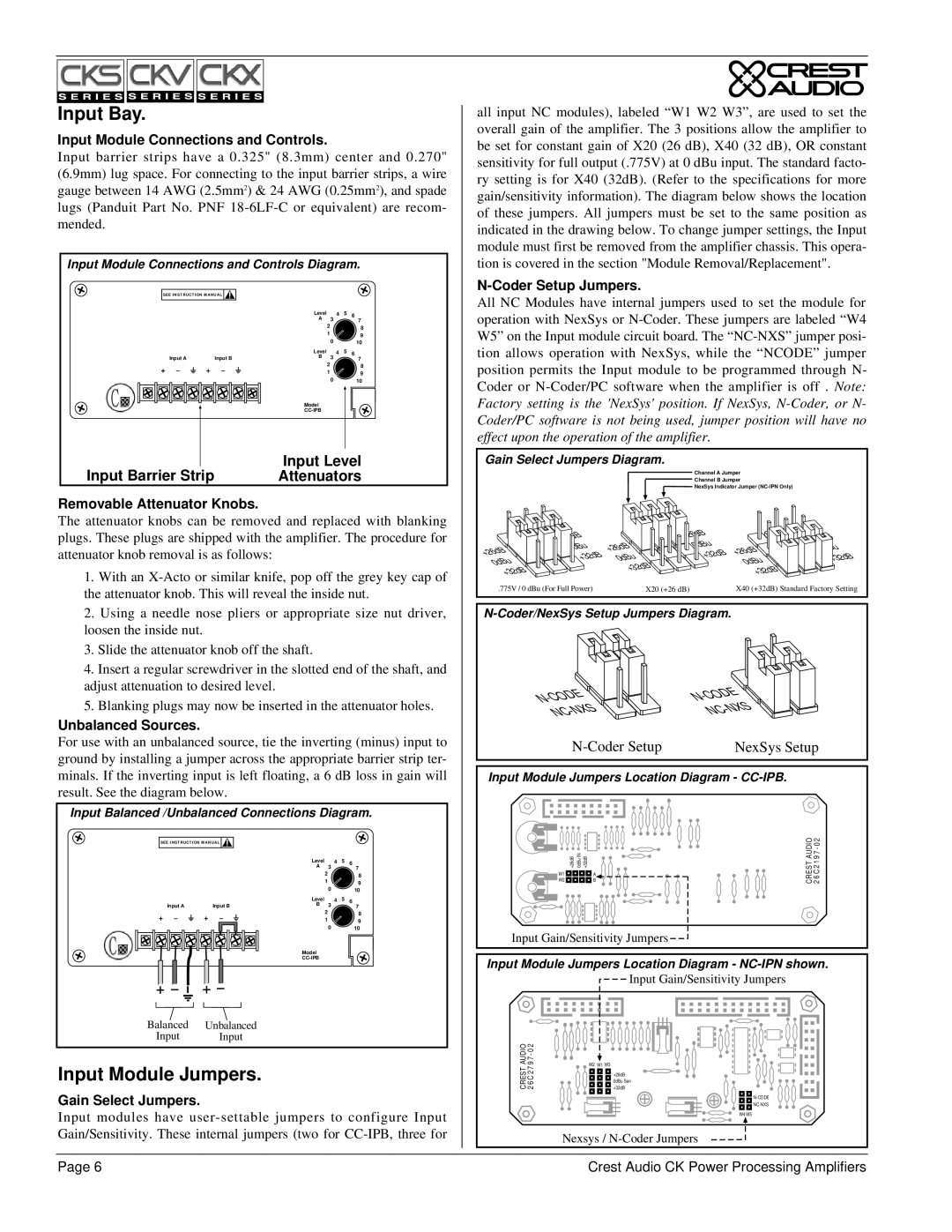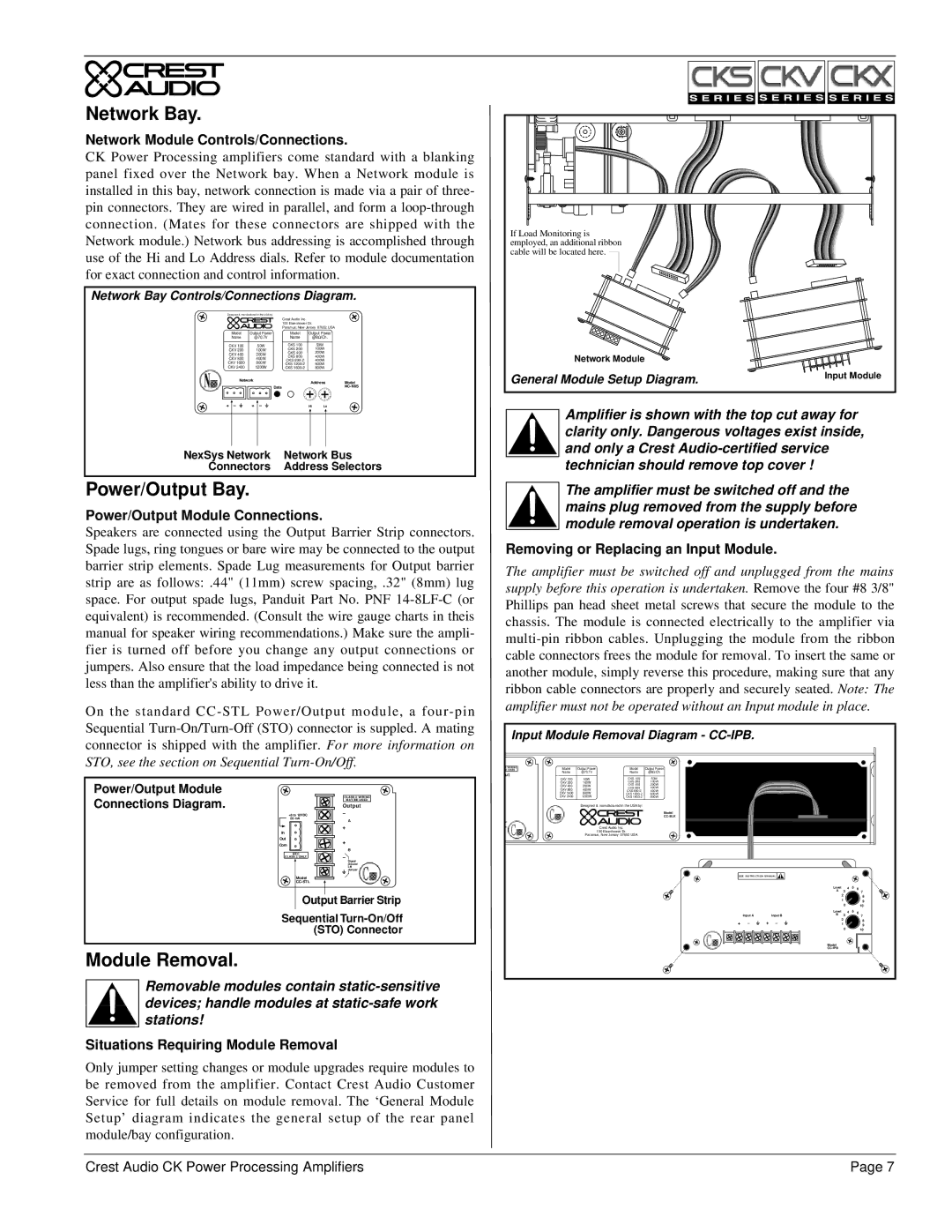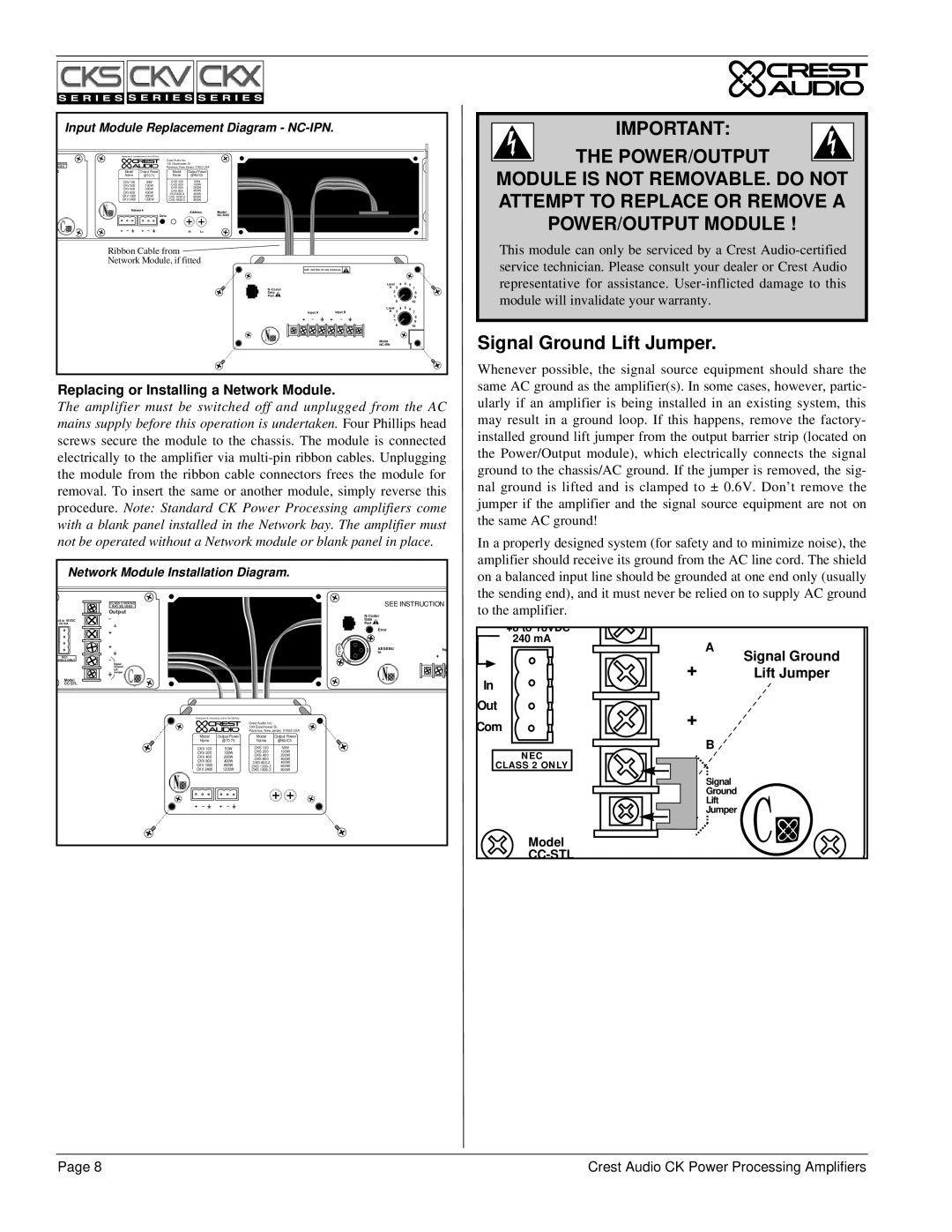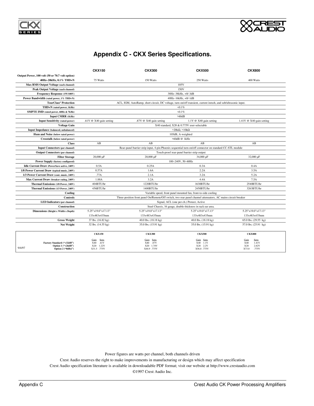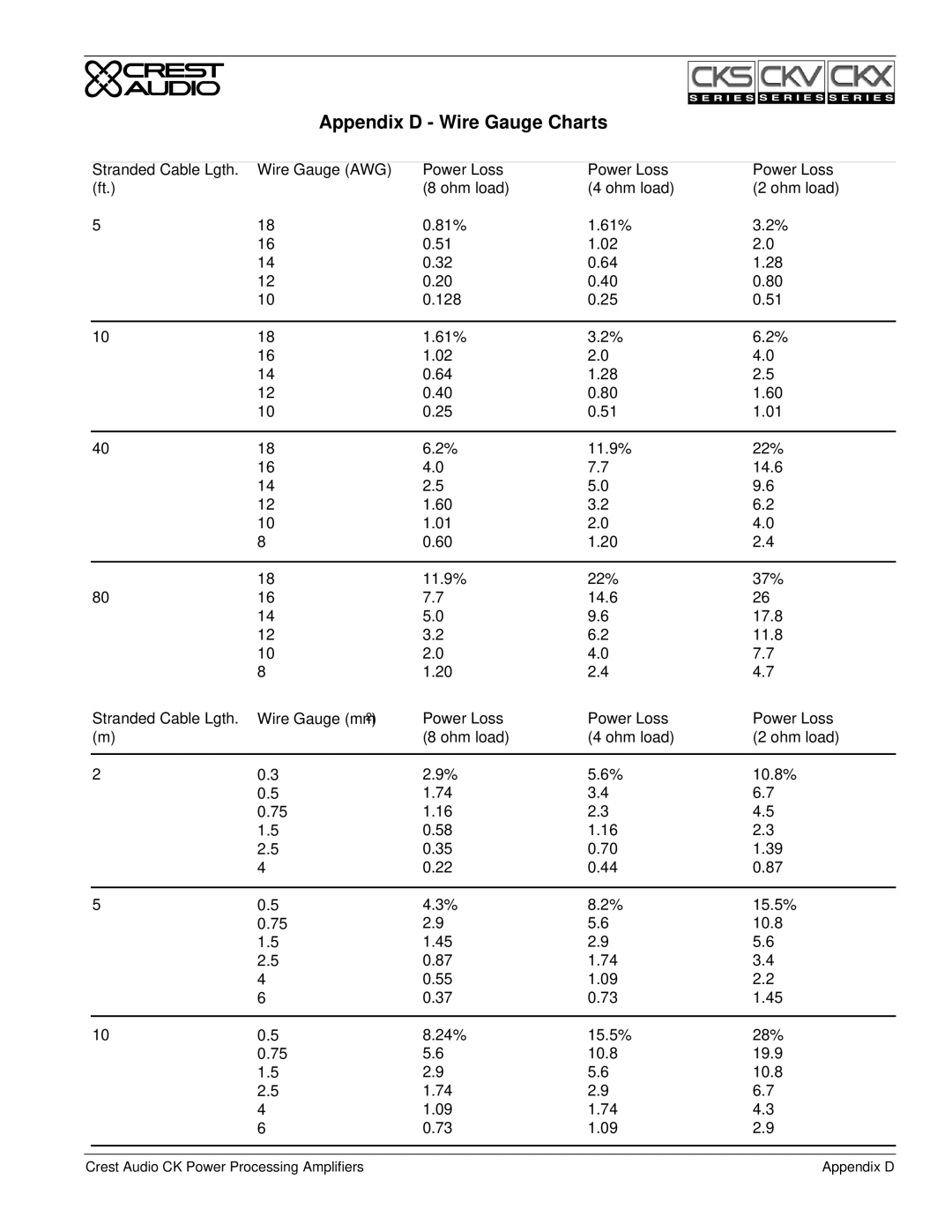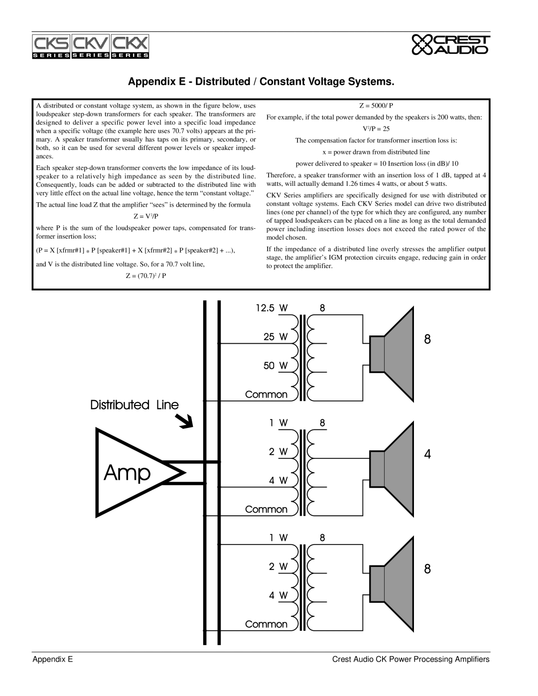
Appendix E - Distributed / Constant Voltage Systems.
A distributed or constant voltage system, as shown in the figure below, uses |
|
|
|
|
|
|
|
|
| Z = 5000/ P | ||||||||||||
loudspeaker | For example, if the total power demanded by the speakers is 200 watts, then: | |||||||||||||||||||||
designed to deliver a specific power level into a specific load impedance | ||||||||||||||||||||||
|
|
|
|
|
|
|
|
|
| V2/P = 25 | ||||||||||||
when a specific voltage (the example here uses 70.7 volts) appears at the pri- |
|
|
|
|
|
|
|
|
|
| ||||||||||||
|
|
|
|
|
|
|
|
|
|
|
|
| ||||||||||
mary. A speaker transformer usually has taps on its primary, secondary, or |
|
|
| The compensation factor for transformer insertion loss is: | ||||||||||||||||||
both, so it can be used for several different power levels or speaker imped- |
|
|
|
|
|
|
|
| x = power drawn from distributed line | |||||||||||||
ances. |
|
|
|
|
|
|
|
| ||||||||||||||
|
|
| power delivered to speaker = 10 Insertion loss (in dB)/ 10 | |||||||||||||||||||
Each speaker |
|
|
| |||||||||||||||||||
Therefore, a speaker transformer with an insertion loss of 1 dB, tapped at 4 | ||||||||||||||||||||||
speaker to a relatively high impedance as seen by the distributed line. | ||||||||||||||||||||||
Consequently, loads can be added or subtracted to the distributed line with | watts, will actually demand 1.26 times 4 watts, or about 5 watts. | |||||||||||||||||||||
very little effect on the actual line voltage, hence the term “constant voltage.” | CKV Series amplifiers are specifically designed for use with distributed or | |||||||||||||||||||||
|
|
|
|
|
|
|
|
| ||||||||||||||
The actual line load Z that the amplifier “sees” is determined by the formula | constant voltage systems. Each CKV Series model can drive two distributed | |||||||||||||||||||||
|
| Z = V2/P | lines (one per channel) of the type for which they are configured, any number | |||||||||||||||||||
|
| of tapped loudspeakers can be placed on a line as long as the total demanded | ||||||||||||||||||||
where P is the sum of the loudspeaker power taps, compensated for trans- | ||||||||||||||||||||||
power including insertion losses does not exceed the rated power of the | ||||||||||||||||||||||
former insertion loss; | model chosen. | |||||||||||||||||||||
(P = X [xfrmr#1] * P [speaker#1] + X [xfrmr#2] * P [speaker#2] + ...), | If the impedance of a distributed line overly stresses the amplifier output | |||||||||||||||||||||
and V is the distributed line voltage. So, for a 70.7 volt line, | stage, the amplifier’s IGM protection circuits engage, reducing gain in order | |||||||||||||||||||||
to protect the amplifier. | ||||||||||||||||||||||
| Z = (70.7)2 / P |
|
|
|
|
|
|
|
|
|
|
|
|
| ||||||||
|
|
|
|
|
|
|
|
|
|
|
|
|
|
|
|
|
|
|
|
|
| |
|
|
|
|
|
|
|
|
|
|
|
|
|
|
|
|
|
|
|
|
|
| |
|
|
|
|
|
|
|
|
|
|
|
|
|
|
|
|
|
|
|
|
|
| |
|
|
|
|
|
|
|
|
|
|
|
|
|
|
|
|
|
|
|
|
|
| |
|
|
|
|
|
|
|
|
|
|
|
|
|
|
|
|
|
|
|
|
|
| |
|
|
|
|
|
|
|
|
|
|
|
|
|
|
|
|
|
|
|
|
|
| |
|
|
|
|
|
|
|
|
|
|
|
|
|
|
|
|
|
|
|
|
|
| |
|
|
|
|
|
|
|
|
|
|
|
|
|
|
|
|
|
|
|
|
|
| |
|
|
|
|
|
|
|
|
|
|
|
|
|
|
|
|
|
|
|
|
|
| |
|
|
|
|
|
|
|
|
|
|
|
|
|
|
|
|
|
|
|
|
|
| |
|
|
|
|
|
|
|
|
|
|
|
|
|
|
|
|
|
|
|
|
|
| |
|
|
|
|
|
|
|
|
|
|
|
|
|
|
|
|
|
|
|
|
|
| |
|
|
|
|
|
|
|
|
|
|
|
|
|
|
|
|
|
|
|
|
|
| |
|
|
|
|
|
|
|
|
|
|
|
|
|
|
|
|
|
|
|
|
|
| |
|
|
|
|
|
|
|
|
|
|
|
|
|
|
|
|
|
|
|
|
|
| |
|
|
|
|
|
|
|
|
|
|
|
|
|
|
|
|
|
|
|
|
|
| |
|
|
|
|
|
|
|
|
|
|
|
|
|
|
|
|
|
|
|
|
|
| |
|
|
|
|
|
|
|
|
|
|
|
|
|
|
|
|
|
|
|
|
|
| |
|
|
|
|
|
|
|
|
|
|
|
|
|
|
|
|
|
|
|
|
|
| |
|
|
|
|
|
|
|
|
|
|
|
|
|
|
|
|
|
|
|
|
|
| |
|
|
|
|
|
|
|
|
|
|
|
|
|
|
|
|
|
|
|
|
|
| |
|
|
|
|
|
|
|
|
|
|
|
|
|
|
|
|
|
|
|
|
|
| |
|
|
|
|
|
|
|
|
|
|
|
|
|
|
|
|
|
|
|
|
|
| |
|
|
|
|
|
|
|
|
|
|
|
|
|
|
|
|
|
|
|
|
|
| |
|
|
|
|
|
|
|
|
|
|
|
|
|
|
|
|
|
|
|
|
|
| |
|
|
|
|
|
|
|
|
|
|
|
|
|
|
|
|
|
|
|
|
|
| |
|
|
|
|
|
|
|
|
|
|
|
|
|
|
|
|
|
|
|
|
|
| |
|
|
|
|
|
|
|
|
|
|
|
|
|
|
|
|
|
|
|
|
|
| |
|
|
|
|
|
|
|
|
|
|
|
|
|
|
|
|
|
|
|
|
|
| |
|
|
|
|
|
|
|
|
|
|
|
|
|
|
|
|
|
|
|
|
|
| |
|
|
|
|
|
|
|
|
|
|
|
|
|
|
|
|
|
|
|
|
|
| |
|
|
|
|
|
|
|
|
|
|
|
|
|
|
|
|
|
|
|
|
|
| |
|
|
|
|
|
|
|
|
|
|
|
|
|
|
|
|
|
|
|
|
|
| |
Appendix E | Crest Audio CK Power Processing Amplifiers |
