Network Bay.
Network Module Controls/Connections.
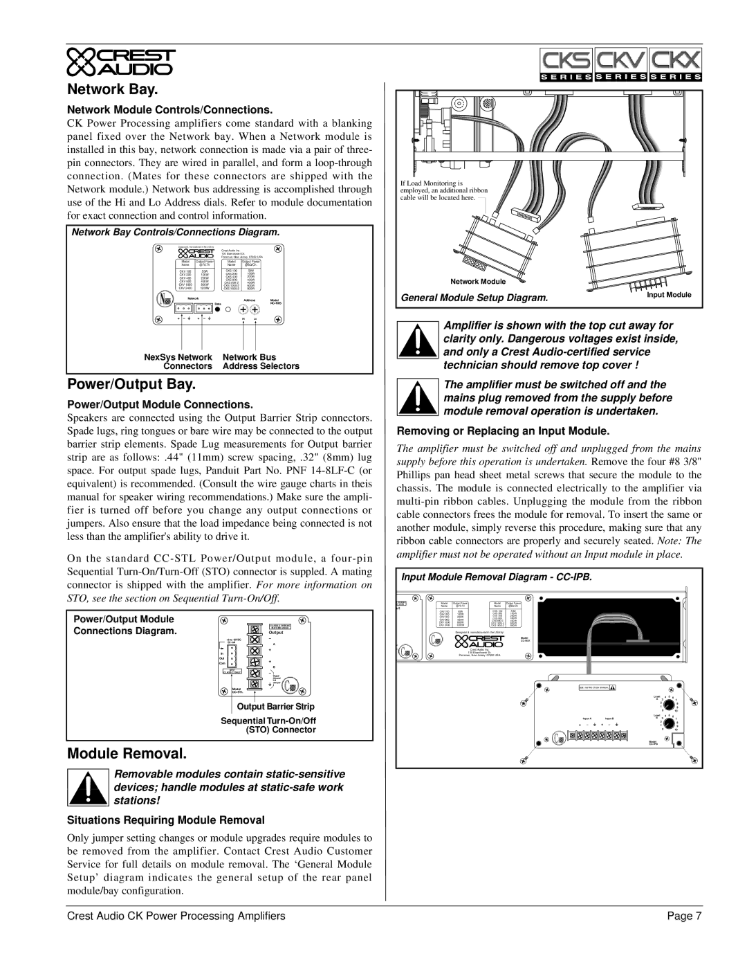
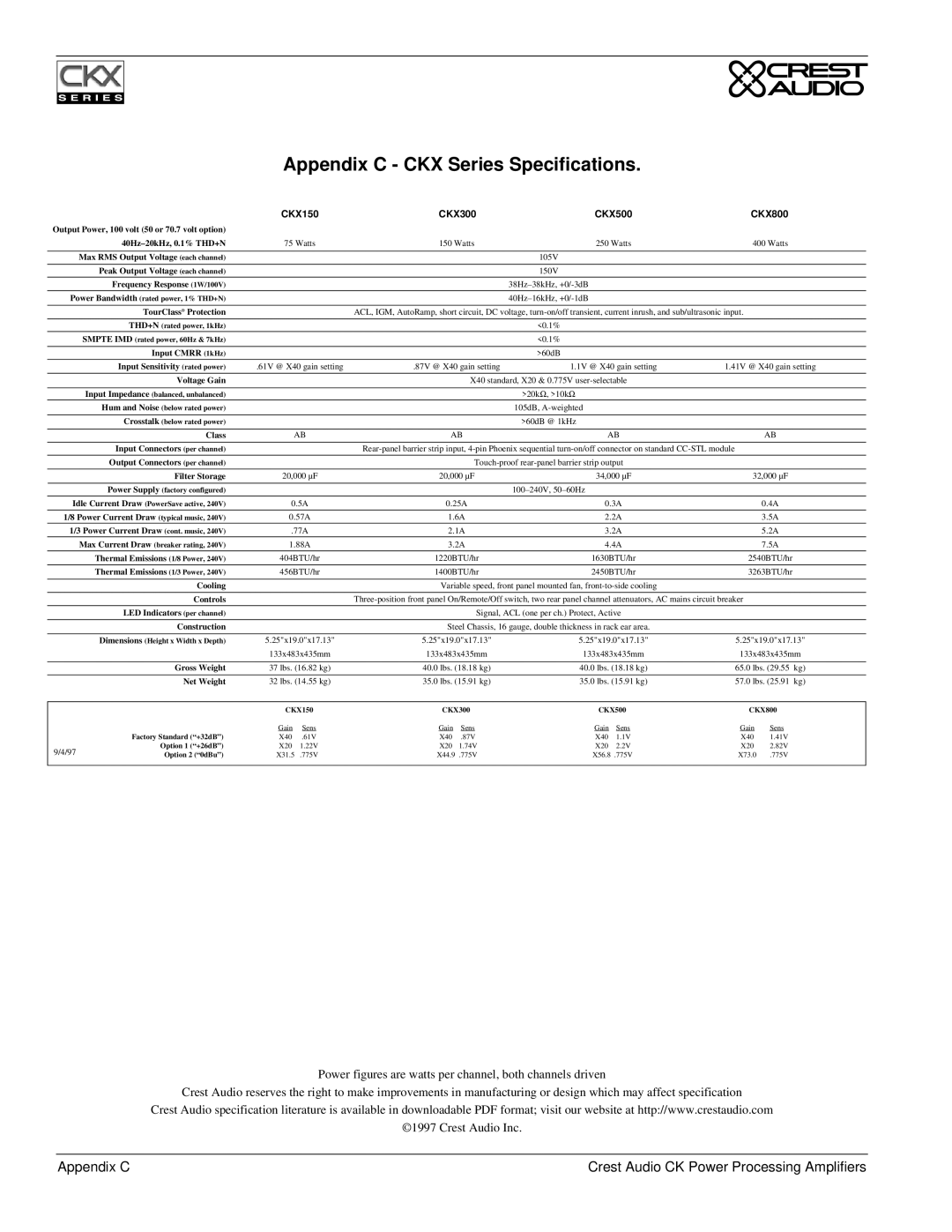
CK Power Processing amplifiers come standard with a blanking panel fixed over the Network bay. When a Network module is installed in this bay, network connection is made via a pair of three- pin connectors. They are wired in parallel, and form a
Network Bay Controls/Connections Diagram.
Designed & manufactured in the USA by: |
|
|
|
|
|
|
| ||||
|
|
|
|
| Crest Audio Inc. |
|
|
|
|
|
|
|
|
|
|
| 100 Eisenhower Dr. |
|
|
|
| ||
|
|
|
|
| Paramus, New Jersey 07652 USA | ||||||
Model | Output Power | Model | Output Power | ||||||||
Name | @70.7V | Name | @8Ω/Ch. | ||||||||
CKV 100 |
| 50W | CKS 100 |
|
| 50W |
|
|
| ||
CKV 200 | 100W | CKS 200 |
| 100W |
|
| |||||
CKV 400 | 200W | CKS 400 |
| 200W |
|
| |||||
CKV 800 | 400W | CKS 800 |
| 400W |
|
| |||||
CKS |
| 400W |
|
| |||||||
CKV 1600 | 800W | CKS |
| 600W |
|
| |||||
CKV 2400 | 1200W | CKS |
| 800W |
|
| |||||
| Network |
| Address |
| Model | ||||||
|
|
|
|
| Data | FE |
| 0 |
| ||
|
|
|
|
| 1 | 1 | F E | ||||
|
|
|
|
| 3 |
| D | 3 |
|
| D |
|
|
|
|
| 45 |
| C | 45 |
|
| C |
|
|
|
|
| 6 |
| B | 6 |
|
| B |
|
|
|
|
| 7 | 9 |
| 7 | 8 | 9 |
|
+ | – | + | – |
| Hi |
| Lo | ||||
|
|
|
|
|
|
|
|
|
|
|
|
|
|
|
|
|
|
|
|
|
|
|
|
NexSys Network | Network Bus |
Connectors | Address Selectors |
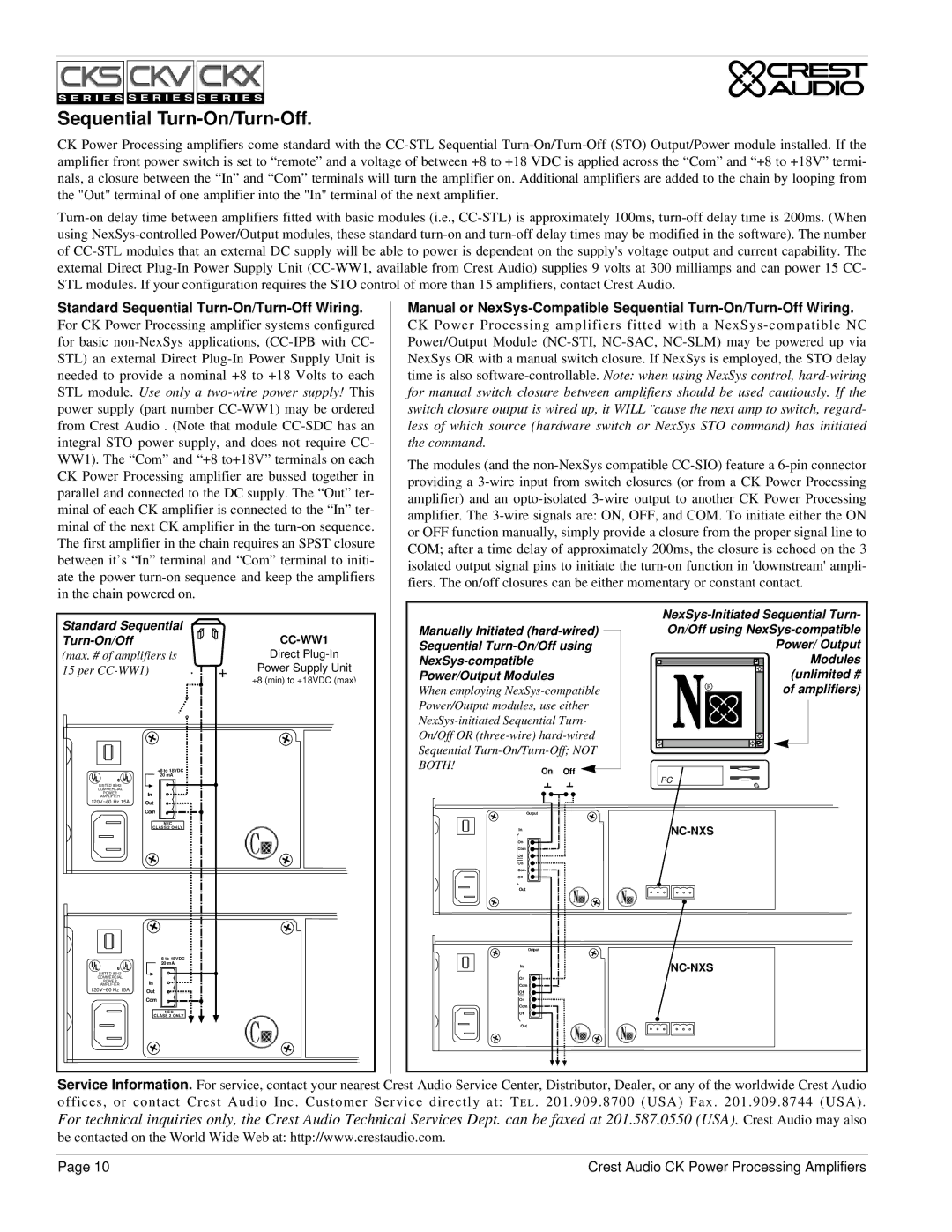
Power/Output Bay.
Power/Output Module Connections.
Speakers are connected using the Output Barrier Strip connectors. Spade lugs, ring tongues or bare wire may be connected to the output barrier strip elements. Spade Lug measurements for Output barrier strip are as follows: .44" (11mm) screw spacing, .32" (8mm) lug space. For output spade lugs, Panduit Part No. PNF
On the standard
Power/Output Module
Connections Diagram. | CLASS 2 WIRING | |
MAY BE USED | ||
Output | ||
+8 to 18VDC | – | |
20 mA | A | |
| ||
In | + | |
| ||
Out | + | |
Com | ||
NEC | B | |
– | ||
CLASS 2 ONLY | ||
| Signal | |
| Ground | |
| Lift | |
| Jumper | |
Model |
| |
| ||
Output Barrier Strip | ||
Sequential | ||
| (STO) Connector | |
Module Removal.
Removable modules contain
Situations Requiring Module Removal
Only jumper setting changes or module upgrades require modules to be removed from the amplifier. Contact Crest Audio Customer Service for full details on module removal. The ‘General Module Setup’ diagram indicates the general setup of the rear panel module/bay configuration.
If Load Monitoring is employed, an additional ribbon cable will be located here.
Network Module |
|
General Module Setup Diagram. | Input Module |
|
Amplifier is shown with the top cut away for clarity only. Dangerous voltages exist inside, and only a Crest
The amplifier must be switched off and the mains plug removed from the supply before module removal operation is undertaken.
Removing or Replacing an Input Module.
The amplifier must be switched off and unplugged from the mains supply before this operation is undertaken. Remove the four #8 3/8" Phillips pan head sheet metal screws that secure the module to the chassis. The module is connected electrically to the amplifier via
Input Module Removal Diagram - CC-IPB.
2 WIRING | Model | Output Power | Model | Output Power |
BE USED | ||||
ut | Name | @70.7V | Name | @8Ω/Ch. |
|
| CKS 100 | 50W | |
| CKV 100 | 50W | ||
| CKV 200 | 100W | CKS 200 | 100W |
| CKV 400 | 200W | CKS 400 | 200W |
| CKV 800 | 400W | CKS 800 | 400W |
| CKS | 400W | ||
| CKV 1600 | 800W | CKS | 600W |
| CKV 2400 | 1200W | CKS | 800W |
Designed & manufactured in the USA by:
Model
l |
|
nd |
|
er | Crest Audio Inc. |
| 100 Eisenhower Dr. |
| Paramus, New Jersey 07652 USA |
SEE INSTRUCTION MANUAL
|
|
|
| Level |
| 4 | 5 | 6 |
|
|
|
| A | 3 |
|
| 7 |
|
|
|
|
| 2 |
|
| 8 |
|
|
|
|
| 1 |
|
| 9 |
|
|
|
|
| 0 |
|
| 10 |
|
|
|
| Level |
| 4 | 5 | 6 |
| Input A |
| Input B | B | 3 |
|
| 7 |
+ | – | + | – |
| 2 |
|
| 8 |
| 1 |
|
| 9 | ||||
|
|
|
|
| 0 |
|
| 10 |
|
|
|
| Model |
|
|
|
|
|
|
|
|
|
|
|
|
Crest Audio CK Power Processing Amplifiers | Page 7 |
