AV-P960E specifications
The JVC AV-P960E is a distinguished component in the realm of professional video cassette recorders, especially appreciated for its advanced features, remarkable technologies, and robust characteristics that cater to both broadcast professionals and serious enthusiasts alike. Launched in an era when analog devices were poised for transition, the AV-P960E exemplifies JVC's commitment to innovation and high-quality performance.At the core of the JVC AV-P960E lies its versatile playback and recording capabilities, supporting a variety of tape formats, including S-VHS and VHS. This versatility enables users to work seamlessly with a range of media, accommodating different production needs. The device is equipped with dual-mode recording, allowing for both standard and extended play, ensuring users can choose between quality and duration based on project requirements.
One of the standout features of the AV-P960E is its Super VHS functionality, which elevates video quality significantly compared to standard VHS. This technology utilizes improved resolution and a wider frequency response, which translates to sharper images and clearer audio. The inclusion of a high-quality decoder plays a crucial role in maintaining the fidelity of the original recording during playback, making the JVC AV-P960E an ideal choice for professionals seeking to archive high-quality footage.
Another notable characteristic of this model is its user-friendly interface, which includes a comprehensive set of controls and an intuitive menu system. This makes it accessible to users with varying levels of expertise, from newcomers to seasoned professionals. Furthermore, the device boasts features like frame-by-frame playback, which is essential for editing and reviewing footage with precision.
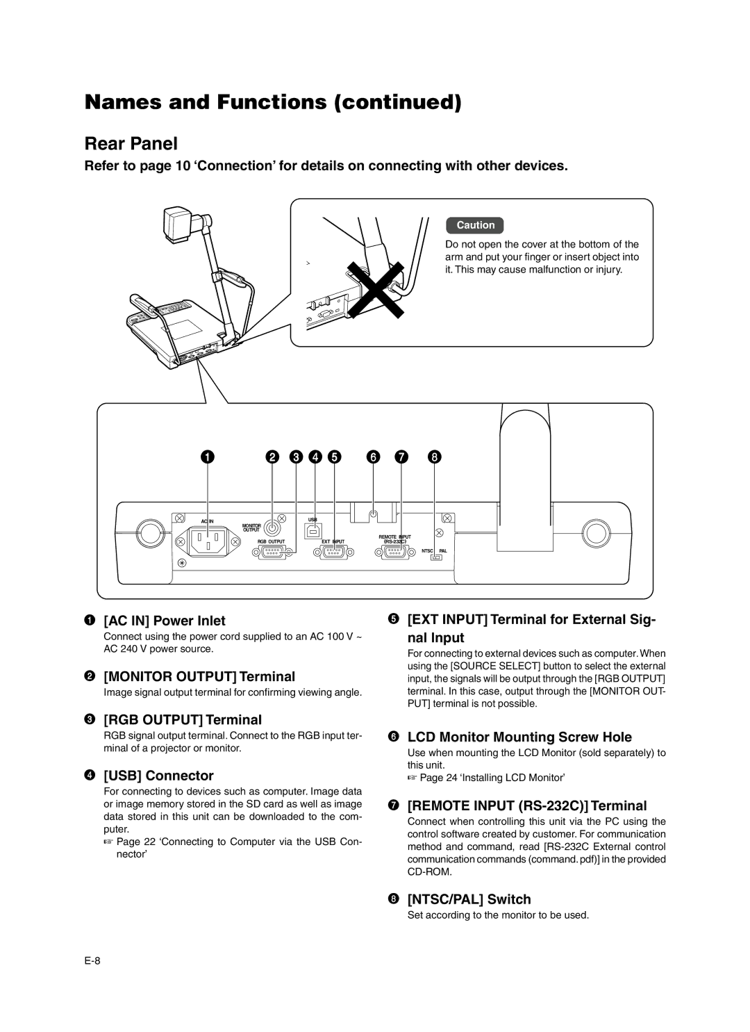
Connectivity options are extensive, with multiple input and output interfaces including composite video, S-Video, and audio connections. This makes it simple to integrate the AV-P960E into a wider video production setup. The robustness of this machine does not stop at its performance; it is built to withstand the rigors of professional use, ensuring reliability and longevity.
In summary, the JVC AV-P960E remains a noteworthy player in the field of video cassette recorders. Its combination of advanced recording features, superior playback quality, user-centric design, and rugged construction makes it a valuable asset for anyone involved in video production. Whether for archiving precious memories or for serious broadcast work, the AV-P960E stands out as a testament to JVC's engineering excellence.

