www.ti.com | EVM Configuration and Description |
3 EVM Configuration and Description
3.1EVM Description
To conform to the USB 2.0 specification, the differential traces D+ and D- lines on the board are impedance matched to
3.2Jumper Configuration (J6 to J8)
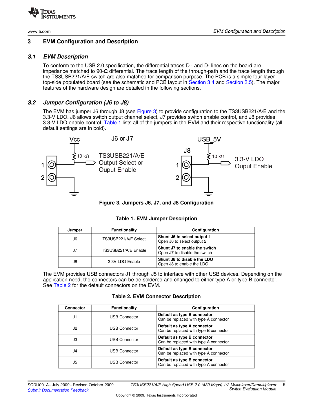
The EVM has jumper J6 through J8 (see Figure 3) to provide configuration to the TS3USB221/A/E and the
![]() 10 kΩ TS3USB221/A/E
10 kΩ TS3USB221/A/E
Output Select or
Ouput Enable
10 kΩ | |
| |
| Ouput Enable |
Figure 3. Jumpers J6, J7, and J8 Configuration
Table 1. EVM Jumper Description
Jumper | Functionality | Configuration | |
|
|
| |
J6 | TS3USB221/A/E Select | Shunt J6 to select output 1 | |
Open J6 to select output 2 | |||
|
| ||
|
|
| |
J7 | TS3USB221/A/E Enable | Shunt J7 to enable the switch | |
Open J7 to disable the switch | |||
|
| ||
|
|
| |
J8 | 3.3V LDO Enable | Shunt J8 to disable the LDO | |
Open J8 to enable the LDO | |||
|
| ||
|
|
|
The EVM provides USB connectors J1 through J5 to interface with other USB devices. Depending on the application need, the connectors can be
Table 2. EVM Connector Description
| Connector | Functionality | Configuration |
| |
|
|
|
|
|
|
| J1 | USB Connector | Default as type B connector |
| |
| Can be replaced with type A connector |
| |||
|
|
|
|
| |
|
|
|
|
|
|
| J2 | USB Connector | Default as type A connector |
| |
| Can be replaced with type B connector |
| |||
|
|
|
|
| |
|
|
|
|
|
|
| J3 | USB Connector | Default as type B connector |
| |
| Can be replaced with type A connector |
| |||
|
|
|
|
| |
|
|
|
|
|
|
| J4 | USB Connector | Default as type B connector |
| |
| Can be replaced with type A connector |
| |||
|
|
|
|
| |
|
|
|
|
|
|
| J5 | USB Connector | Default as type B connector |
| |
| Can be replaced with type A connector |
| |||
|
|
|
|
| |
|
|
|
|
|
|
|
|
|
|
|
|
SCDU001A | TS3USB221/A/E High Speed USB 2.0 (480 Mbps) 1:2 Multiplexer/Demultiplexer 5 | ||||
Submit Documentation Feedback |
|
| Switch Evaluation Module | ||
|
|
|
| ||
Copyright © 2009, Texas Instruments Incorporated