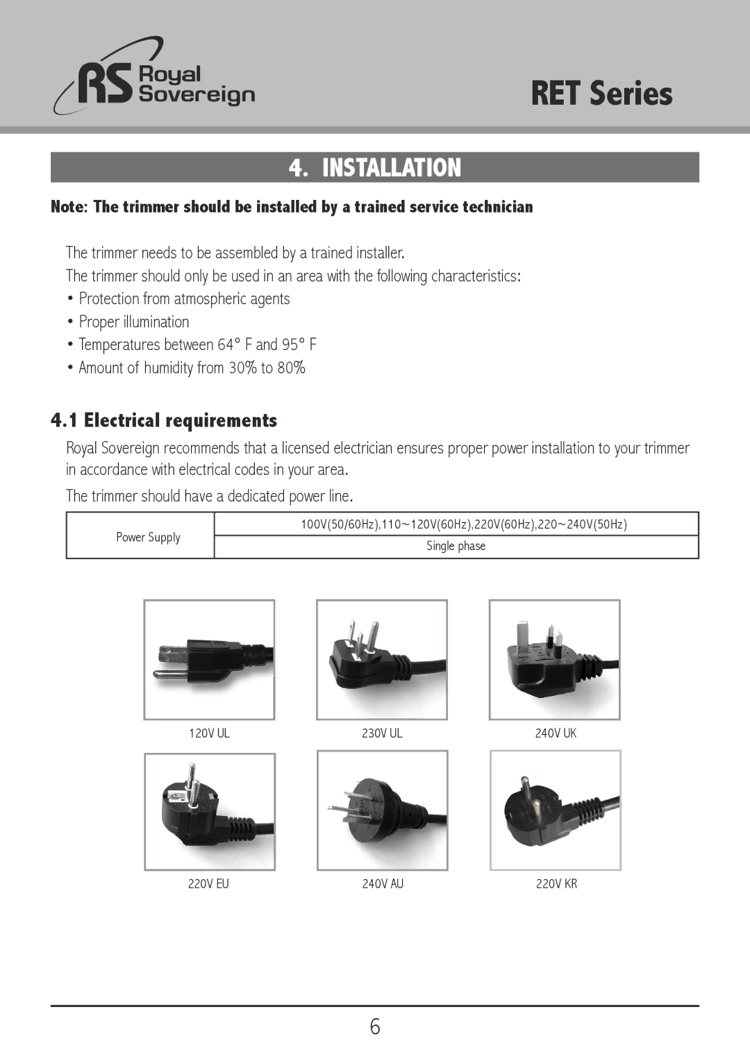
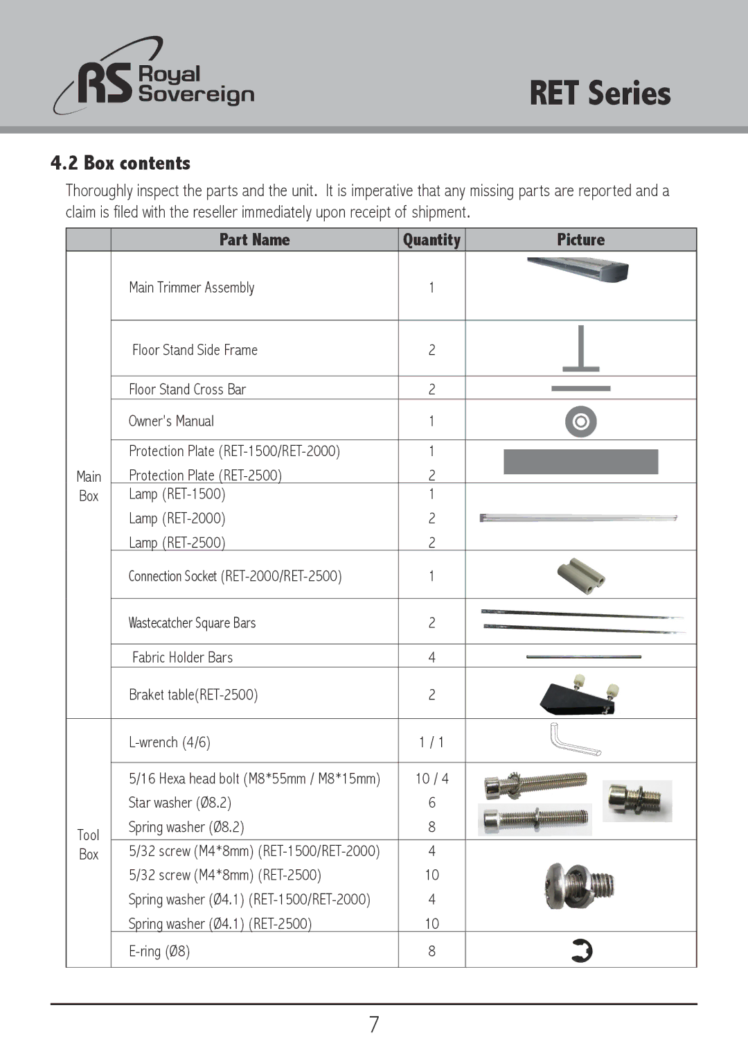
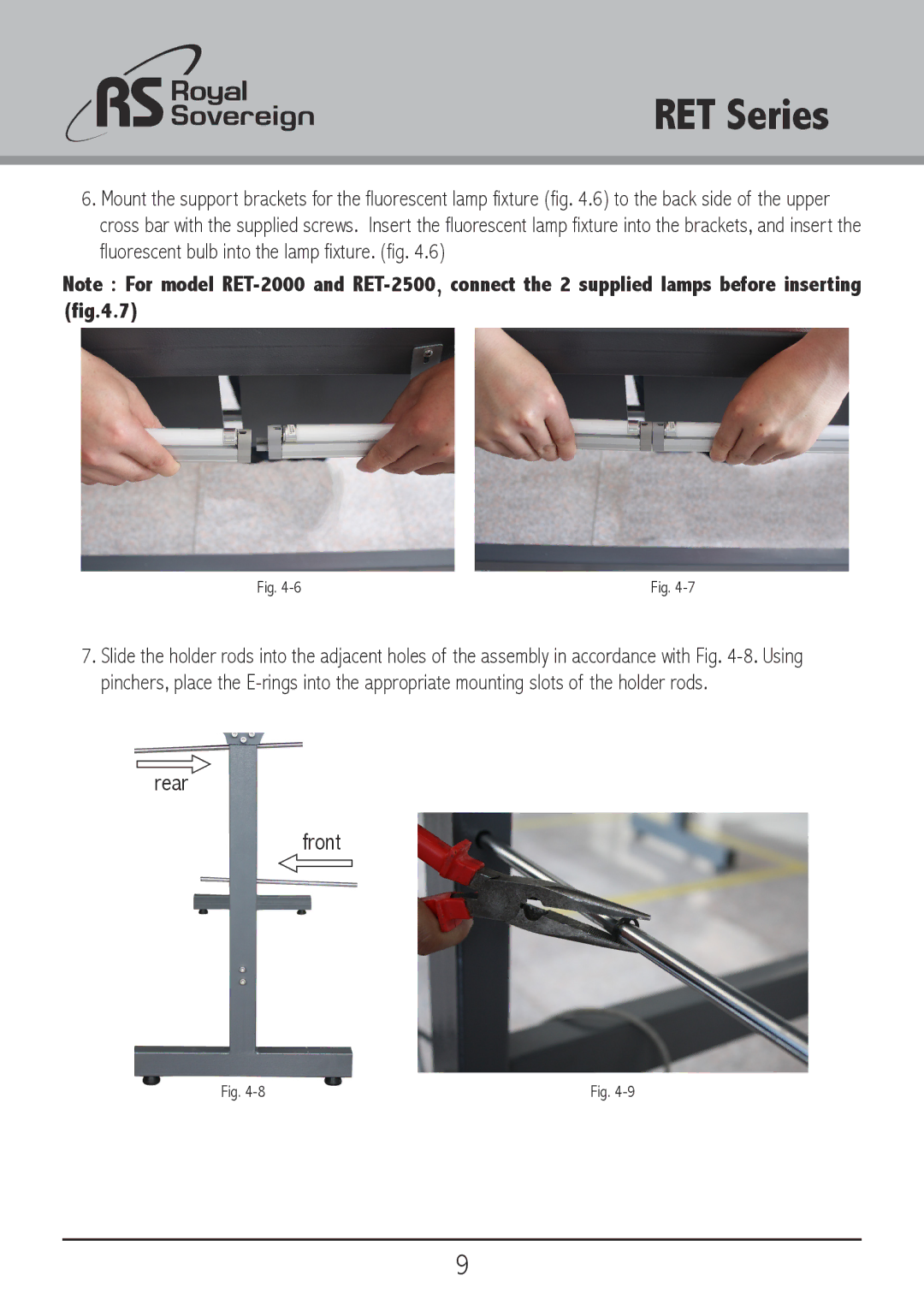
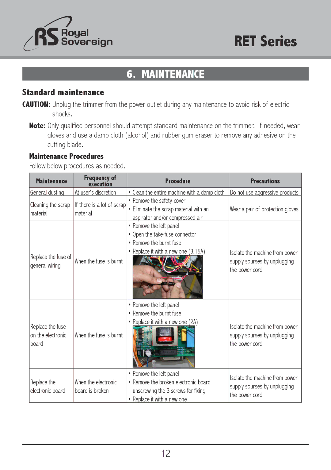
3D Connexion RET-2500, RET-2000, RET-1500 owner manual Trimmer is now ready for Operation. Fig

Page 10

RET Series

8.Screw the wastecatcher square bars into the previously inserted wastecatcher holder rods, (Fig. 4-10) putting the supplied screws through the largest drilling in the square bar, so that the head of the screw sits flush within the bar itself. (Fig. 4-11)

Fig. 4-10

Fig. 4-11

9.Position the main trimmer assembly on top of the floor stand. And properly align the bolt holes. Use bolts (M8x55) to attach the main trimmer assembly to the floor stand. (Fig. 4-12)

Fig. 4-12

10.Plug the lamp cable into the socket on the fluorescent lamp fixture. (Fig. 4-13)

11.Connect the power cord in to the AC outlet and turn the Power switch to the ON position.

12.The Trimmer is now ready for Operation. (Fig. 4-14)

Fig. 4-13

Fig. 4-14

10

Image 10
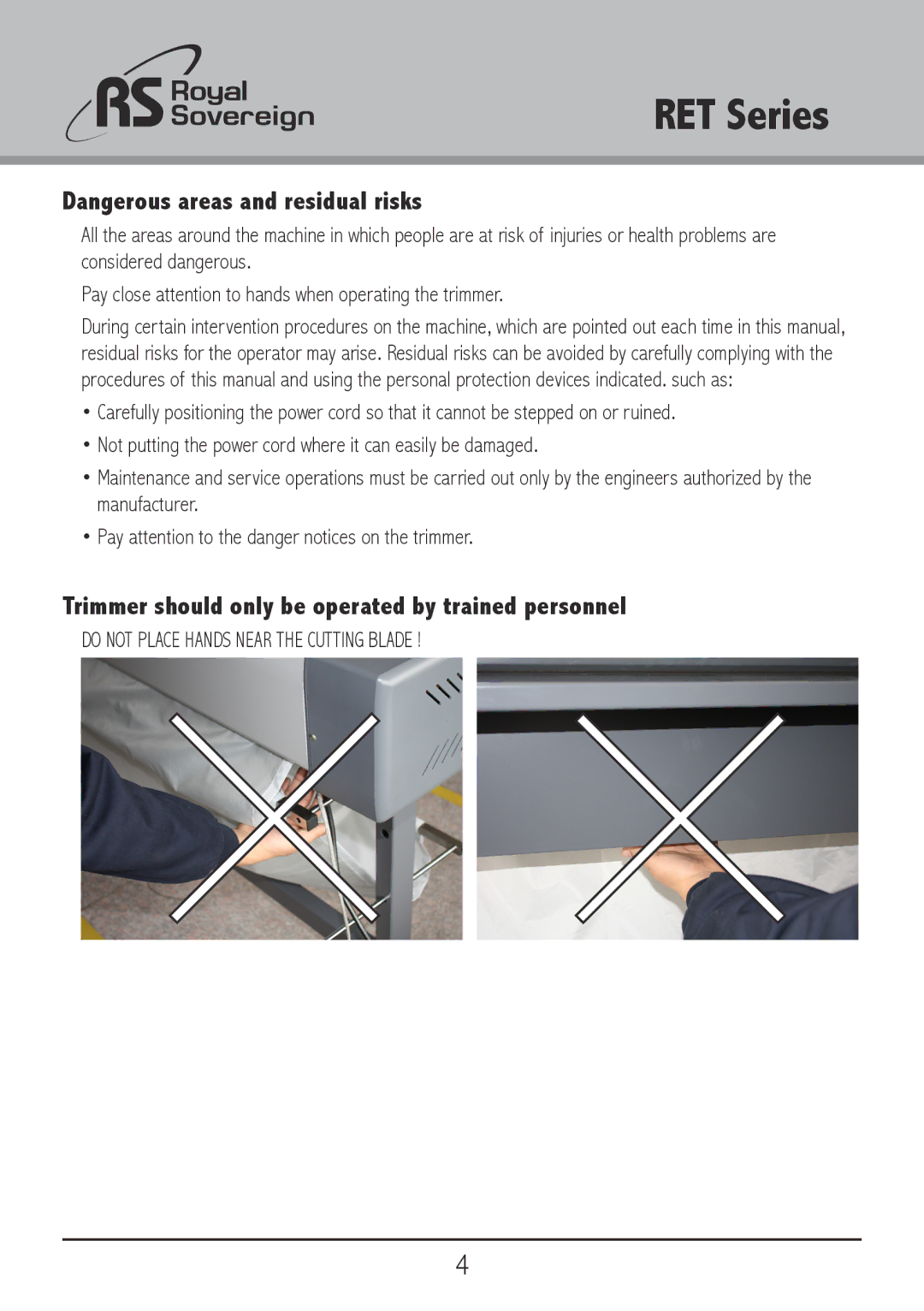
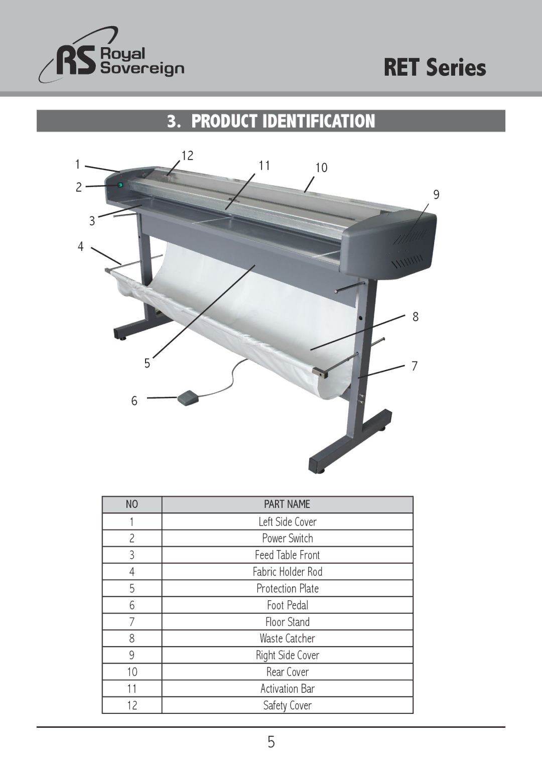
Contents Royal Sovereign International Inc RET Series Keep out of reach of children Safety PrecautionsIntroduction Pay attention to the danger notices on the trimmerTrimmer should only be operated by trained personnel Product Identification Part NameInstallation Electrical requirementsBox contents Assembly Rear Front Trimmer is now ready for Operation. Fig Operation Maintenance Procedures MaintenanceStandard maintenance Follow below procedures as neededTroubleshooting Recommended Trimming Materials Technical informationWarranty RS Canada INC