Carrier 48TJE008-014, 48TJD008-014, 48TJF008-012 installation instructions Electrical Data

Page 9

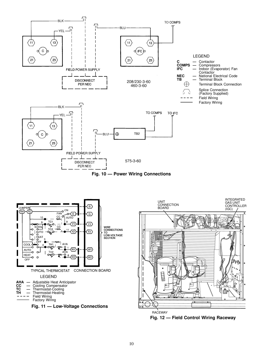
Route thermostat cable or equivalent single leads of col- ored wire from subbase terminals to low-voltage connec- tions on unit (shown in Fig. 11) as described in Steps 1 - 4 below.

1.If unit is mounted on roof curb and accessory thru-the- curb service plate connection is used, route wire through connection plate.

2.Pass control wires through the hole provided on unit (see connection D in Connection Sizes table in Fig. 7).

3.Feed wires through the raceway built into the corner post to the 24-v barrier located on the left side of the control

box. See Fig. 12. The raceway provides the UL-required (Underwriters' Laboratories) clearance between high- and low-voltage wiring.

4.Connect thermostat wires to screw terminals on low- voltage connection board.

HEAT ANTICIPATOR SETTINGS Ð Set heat anticipator settings at .14 amp for the ®rst stage and .20 amp for second- stage heating.

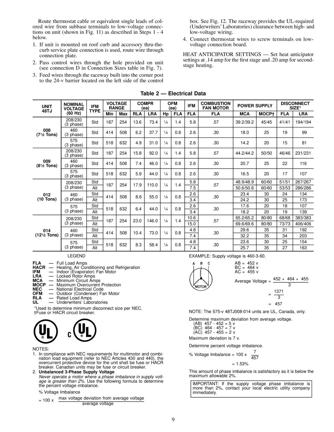
Table 2 Ð Electrical Data

UNIT

NOMINAL

IFM

VOLTAGE

COMPR

OFM

IFM

COMBUSTION

POWER SUPPLY

DISCONNECT

VOLTAGE

RANGE

(ea)


(ea)

FAN MOTOR

SIZE*

48TJ

TYPE


(60 Hz)

Min

Max

RLA

LRA

Hp


FLA

FLA

FLA

MCA

MOCP²

FLA

LRA


208/230

Std

187

254

13.6

73.4

1¤4


1.4

5.8

.57

39.2/39.2

45/45

41/41

194/194


(3 phase)


008

460

Std

414

508

6.2

37.7

1¤4


0.8

2.6

.30

18.0

25

19

99

(71¤2 Tons)

(3 phase)


575

Std

518

632

4.9

31.0

1¤4


0.8

2.6

.30

14.2

20

15

81


(3 phase)


208/230

Std

187

254

15.8

92.0

1¤4


1.4

5.8

.57

44.2/44.2

50/50

46/46

231/231


(3 phase)


009

460

Std

414

508

7.4

46.0

1¤4


0.8

2.6

.30

20.7

25

22

116

(81¤2 Tons)

(3 phase)


575

Std

518

632

5.9

44.0

1¤4


0.8

2.6

.30

16.5

20

17

107


(3 phase)


208/230

Std

187

254

17.9

110.0

1¤4


1.4

5.8

.57

48.9/48.9

60/60

51/51

267/267


(3 phase)

Alt


7.5

50.6/50.6

60/60

53/53

286/286


012

460

Std

414

508

8.6

55.0

1¤4


0.8

2.6

.30

23.4

30

24

134

(10 Tons)

(3 phase)

Alt


3.4

24.2

30

25

173


575

Std

518

632

6.4

44.0

1¤4


0.8

2.6

.30

17.6

20

18

107


(3 phase)

Alt


3.4

18.2

20

19

139


208/230

Std

187

254

23.0

146.0

1¤4


1.4

10.6

.57

65.2/65.2

80/80

68/68

383/383


(3 phase)

Alt


15.0

69.6/69.6

80/80

73/73

406/406


014

460

Std

414

508

10.4

73.0

1¤4


0.8

4.8

.30

29.6

35

31

192

(121¤2 Tons)

(3 phase)

Alt


7.4

32.2

35

34

203


575

Std

518

632

8.3

58.4

1¤4


0.8

4.8

.30

23.6

30

25

154


(3 phase)

Alt


7.4

25.7

35

27

163


LEGEND

FLA

Ð Full Load Amps

HACR

Ð Heating, Air Conditioning and Refrigeration

IFM

Ð Indoor (Evaporator) Fan Motor

LRA

Ð Locked Rotor Amps

MCA

Ð Minimum Circuit Amps

EXAMPLE: Supply voltage is 460-3-60.

AB = 452 v

BC = 464 v

AC = 455 v

Average Voltage = 452 + 464 + 455

MOCP Ð Maximum Overcurrent Protection

NEC

Ð National Electrical Code

OFM

Ð Outdoor (Condenser) Fan Motor

RLA

Ð Rated Load Amps

UL

Ð Underwriters' Laboratories

=

3

1371

3

*Used to determine minimum disconnect size per NEC. ²Fuse or HACR circuit breaker.

= 457

NOTE: The 575-v 48TJ008-014 units are UL, Canada, only.

Determine maximum deviation from average voltage. (AB) 457 - 452 = 5 v

(BC) 464 - 457 = 7 v

(AC) 457 - 455 = 2 v Maximum deviation is 7 v.

Determine percent voltage imbalance.

NOTES:

1. In compliance with NEC requirements for multimotor and combi-

% Voltage Imbalance = 100 x

7

nation load equipment (refer to NEC Articles 430 and 440), the

overcurrent protective device for the unit shall be fuse or HACR

breaker. Canadian units may be fuse or circuit breaker.

2. Unbalanced 3-Phase Supply Voltage

Never operate a motor where a phase imbalance in supply volt-

age is greater than 2%. Use the following formula to determine

the percent voltage imbalance.

% Voltage Imbalance

= 100 x

max voltage deviation from average voltage


average voltage


457

= 1.53%

This amount of phase imbalance is satisfactory as it is below the maximum allowable 2%.

IMPORTANT: If the supply voltage phase imbalance is more than 2%, contact your local electric utility company immediately.

9

Image 9
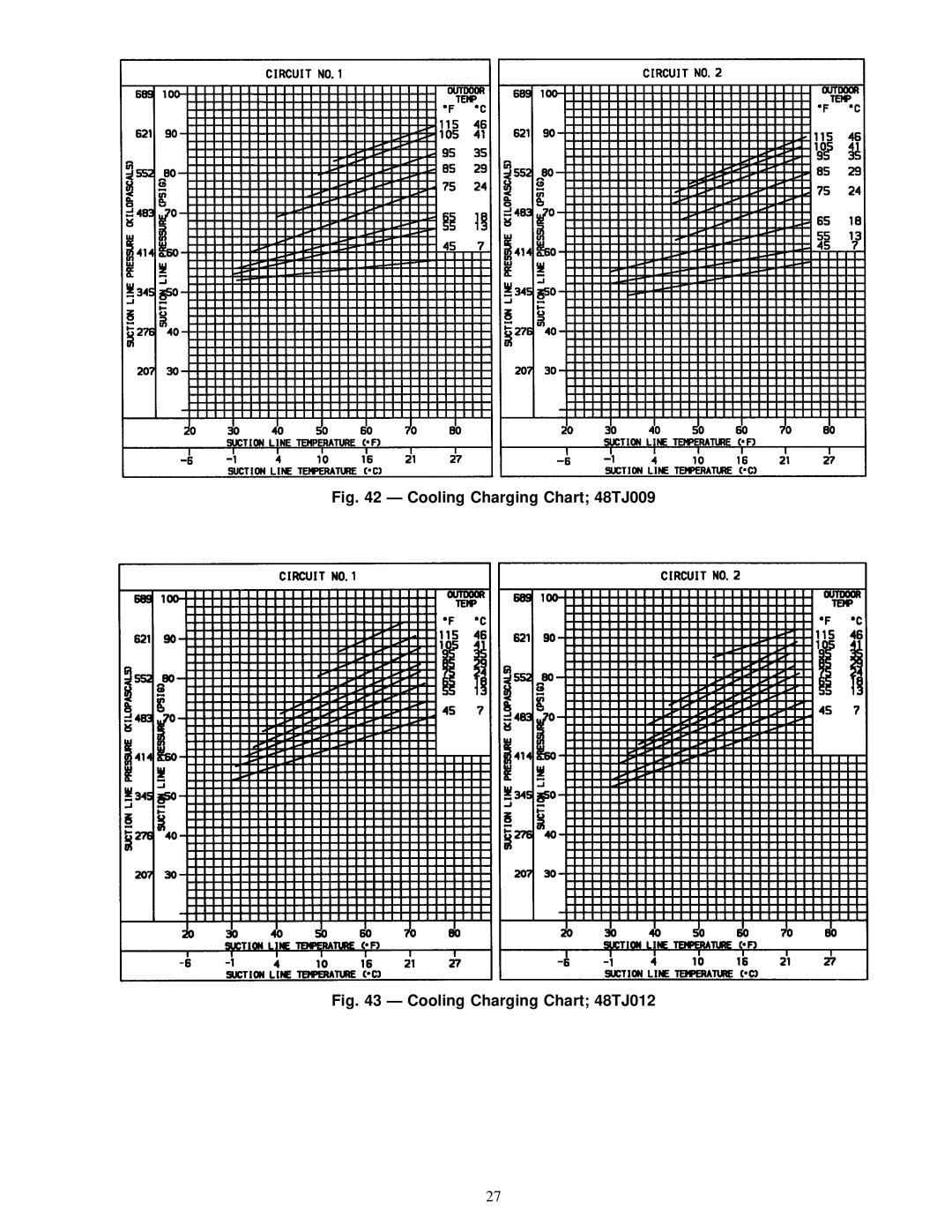
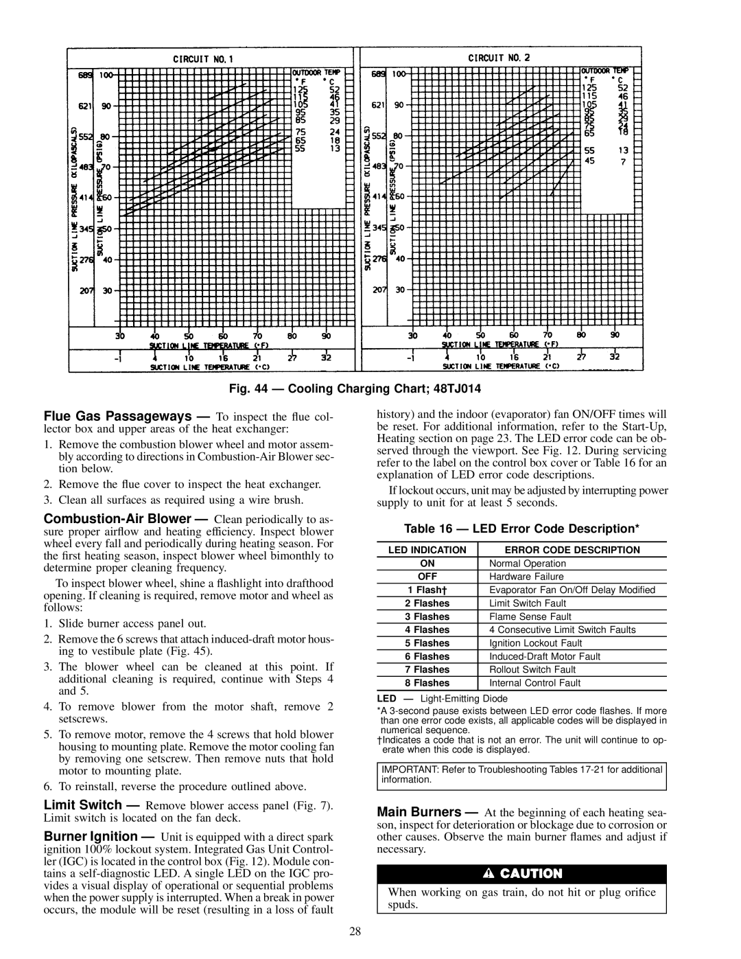
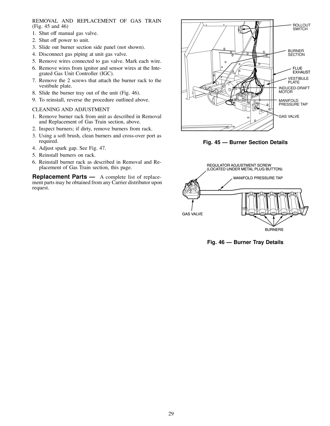
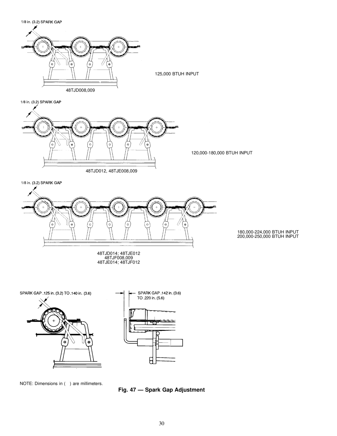
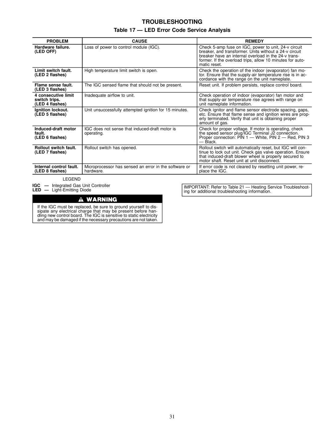
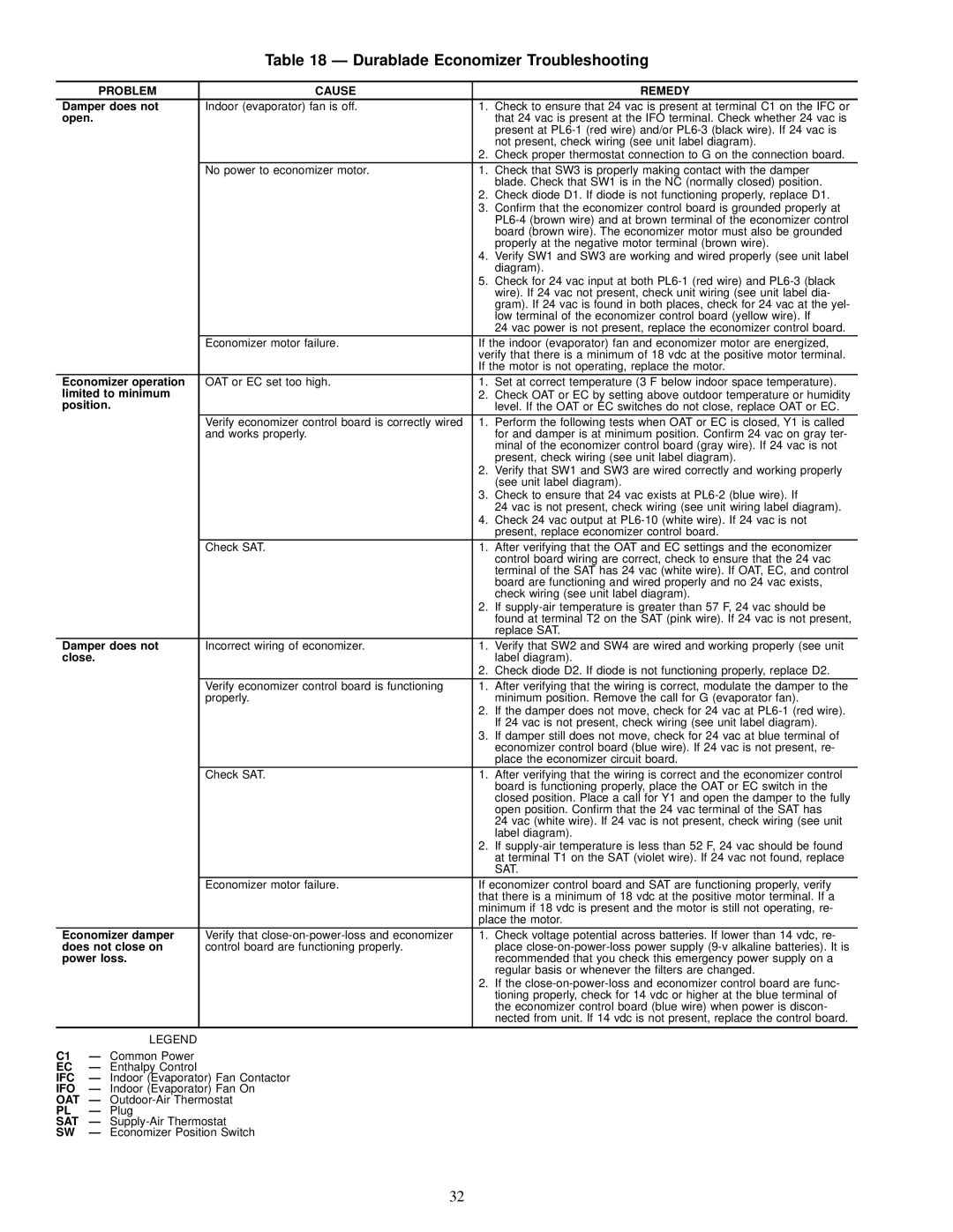
Contents Installation, Start-Up Service Instructions Horizontal Conversion Panels Install External Trap for Condensate``D ALT Drain Hole Accessory Power Control ConnectorUnit Size GAS Connection PackageUnit Leveling Tolerances Physical Data Freeze Protection Thermostat F² Furnace SectionOUTDOOR-AIR Inlet Screens RETURN-AIR FiltersBase Unit Dimensions Flue Hood Details Make Electrical ConnectionsElectrical Data IFC CompsTypical Unit Adjust Factory-Installed OptionsPosition Setting Durablade Economizer Installed in Unit Durablade Economizer Damper Minimum Position Setting Parablade Economizer Installed in Unit Enthalpy Settings for Parablade Economizer Unit Motor Pulley Turns Open Evaporator-Fan Motor Efficiency Economizer Static Pressure Drop in. wgMotor Data Fan Performance, 48TJ008 Ð Vertical Discharge Units Fan Performance, 48TJ009 Ð Vertical Discharge UnitsAirflow Fan Performance, 48TJ014 Ð Vertical Discharge Units Fan Performance, 48TJ012 Ð Vertical Discharge UnitsFan Performance, 48TJ009 Ð Horizontal Discharge Units Fan Performance, 48TJ008 Ð Horizontal Discharge UnitsFan Performance, 48TJ014 Ð Horizontal Discharge Units Fan Performance, 48TJ012 Ð Horizontal Discharge UnitsHeating START-UPAltitude Compensation Nominal InputElevation Lubrication Cleaning Condenser CoilCondenser-Fan Adjustment Fig 48TJ Unit VoltageFAN Height ``A Cooling Charging Chart 48TJ009 LED Indication Error Code Description LED Error Code DescriptionOFF Flash²Burner Section Details Spark Gap Adjustment LED Error Code Service Analysis Problem Cause RemedyLED OFF Problem Cause Remedy Durablade Economizer TroubleshootingParablade Economizer Service Troubleshooting Cooling Service Troubleshooting Heating Service Troubleshooting Typical Wiring Schematic and Component Arrangement Page Copyright 1996 Carrier Corporation Page Preliminary Information Remove and Store in Job File

48TJF008-012, 48TJD008-014, 48TJE008-014 specifications

Carrier's 48TJD008-014, 48TJE008-014, and 48TJF008-012 series are high-performance packaged rooftop units engineered to meet the heating, ventilation, and air conditioning (HVAC) needs of commercial and industrial applications. These units are renowned for their reliability, energy efficiency, and advanced technologies, making them a popular choice among facility managers and HVAC professionals.

One of the standout features of these Carrier units is their robust construction. Designed to withstand diverse environmental conditions, these units come with durable cabinets that are resistant to corrosion and UV degradation. This durability extends the product lifespan and reduces maintenance needs, providing long-term savings for facility operators.

The series includes models ranging from 8 to 14 tons, catering to a variety of space requirements. Each unit is equipped with a high-efficiency scroll compressor that enhances performance while minimizing energy consumption. This compressor technology guarantees quieter operation, reduced vibrations, and exceptional reliability, which are critical factors in commercial settings.

Energy efficiency is a hallmark of the 48TJD, 48TJE, and 48TJF series. These units come with high Seasonal Energy Efficiency Ratios (SEER) and Energy Efficiency Ratios (EER), which result in lower energy bills and a reduced carbon footprint. The incorporation of advanced digital controls allows for precise temperature management and integration with building management systems, ensuring optimal performance throughout the year.

In terms of comfort features, the Carrier series utilizes variable-speed technology, enabling the fan to adjust its speed according to the load requirements. This results in more consistent temperature control and enhanced indoor air quality. The units also include options for enhanced filtration systems, which can accommodate various filter types, ensuring the removal of airborne particles and allergens.

Installation is simplified with these packaged rooftop units. Their compact design fits well on rooftops or in limited spaces, and they come with factory-installed components, which streamline the setup process. Additionally, the units feature easy access panels for maintenance, allowing technicians to conduct service with minimal disruption to operations.

Finally, Carrier's dedication to innovation is evident in the incorporation of smart technologies within these units. Integrated diagnostics and monitoring systems provide real-time performance data, enabling proactive maintenance and reducing the likelihood of unexpected breakdowns.

In summary, Carrier's 48TJD008-014, 48TJE008-014, and 48TJF008-012 rooftop units are engineered for efficiency, reliability, and comfort. With their durable construction, advanced compressor technology, energy efficiency, comfort features, and ease of installation, these units are ideal for meeting the demanding HVAC needs of commercial spaces.