Unpacking
When unpacking, check to make sure that the item is intact and undamaged. If any parts are missing or broken, please call Harbor Freight Tools at the number shown on the cover of this manual as soon as possible.
Set up
Knife Installation and Adjustment
WARNING! Before working on the knives:
•Wear
•Unplug planer and allow knives to cool completely if used recently.
Note: This planer can only use the standard straight knives. Never try to install any other knives on this planer.
1.Wearing
|
| 8a | |
|
| 8d | |
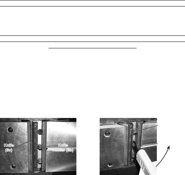
Knife | Knife | 49 | |
Turn | |||
(8c) | Holder (8b) |
this way to loosen knife holder
2.Using provided Wrench (49) turn the Knife Holder Bolts (8d) in the direction shown in the picture to the above right to loosen the Knife Holder (8b) from the Drum. The Bolts thread into the Knife Holder, thus releasing pressure on the drum and allowing the knife holder to be removed.
3.After all Bolts have been threaded into the Knife Holder completely, remove the Knife Holder. Be careful to not move either of the two set screws on the Knife Holder, they keep the knife in alignment.
4.Clean the exposed slot in the Drum.
5.Slide the old Knife (8c) carefully out of the Knife holder.
CAUTION! The Knife has two sharp edges.
Page 9 | For technical questions, please call |