5 CHECK THERMOSTAT OPERATION
CONTINUED FROM FOURTH PAGE
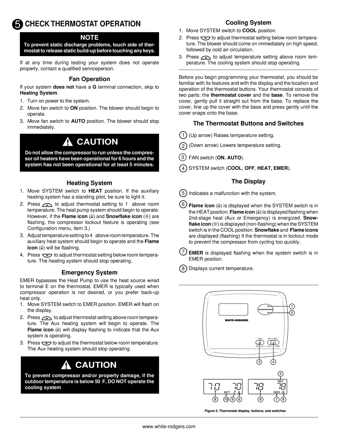
9Displays currently programmed set temperature (this is blank when SYSTEM switch is in the OFF position).
10 “BATT” is displayed when 2 “AAA” batteries are low and should be replaced.
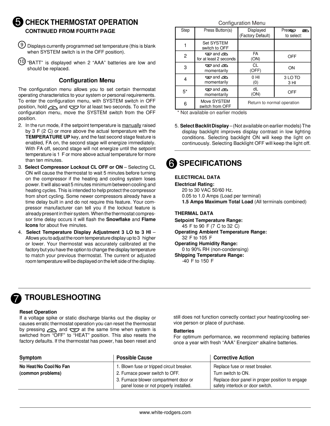
Configuration Menu
The configuration menu allows you to set certain thermostat operating characteristics to your system or personal requirements. To enter the configuration menu, with SYSTEM switch in OFF
position, hold ![]() and
and ![]() for at least two seconds. To exit the configuration menu, move the SYSTEM switch from the OFF position.
for at least two seconds. To exit the configuration menu, move the SYSTEM switch from the OFF position.
Configuration Menu
Step | Press Button(s) | Displayed | Press | or | |
|
| (Factory Default) | to select: | ||
|
|
|
|
| |
1 | Set SYSTEM |
|
|
| |
switch to OFF |
|
|
| ||
|
|
|
| ||
2 | and | FA |
| OFF | |
for at least 2 seconds | (ON) |
| |||
|
|
| |||
|
|
|
|
| |
3 | and | CL |
| ON | |
momentarily | (OFF) |
| |||
|
|
| |||
4 | and | 0 HI | 3 LO TO | ||
momentarily | (0) |
| 3 HI | ||
|
| ||||
5* | and | dL |
| OFF | |
momentarily | (ON) |
| |||
|
|
| |||
6 | Move SYSTEM | Return to normal operation | |||
switch from OFF | |||||
|
|
|
| ||
* Not available on earlier models
2.In the run mode, if the setpoint temperature is manually raised by 3°F (2°C) or more above the actual temperature with the TEMPERATURE UP key, and the fast second stage feature is enabled, FA on, the second stage will energize immediately.
With FA off, second stage will not energize until the setpoint temperature is 1°F or more above actual temperature for more than ten minutes.
3.Select Compressor Lockout CL OFF or ON – Selecting CL ON will cause the thermostat to wait 5 minutes before turning on the compressor if the heating and cooling system loses power. It will also wait 5 minutes minimum between cooling and heating cycles. This is intended to help protect the compressor from short cycling. Some newer compressors already have a time delay built in and do not require this feature. Your com- pressor manufacturer can tell you if the lockout feature is already present in their system. When the thermostat compres- sor time delay occurs it will flash the Snowflake and Flame Icons for about five minutes.
4.Select Temperature Display Adjustment 3 LO to 3 HI – Allows you to adjust the room temperature display up to 3° higher or lower. Your thermostat was accurately calibrated at the factory but you have the option to change the display temperature to match your previous thermostat. The current or adjusted room temperature will be displayed on the left side of the display.
5.Select Backlit Display – (Not available on earlier models) The display backlight improves display contrast in low lighting conditions. Selecting backlight ON will keep the light on continuously. Selecting Backlight OFF will keep the light off.
6 SPECIFICATIONS
ELECTRICAL DATA
Electrical Rating:
20 to 30 VAC 50/60 Hz.
0.05 to 1.0 Amps (Load per terminal)
1.5Amps Maximum Total Load (All terminals combined)
THERMAL DATA
Setpoint Temperature Range:
45°F to 90°F (7°C to 32°C)
Operating Ambient Temperature Range:
32°F to 105°F
Operating Humidity Range:
0 to 90% RH
Shipping Temperature Range:
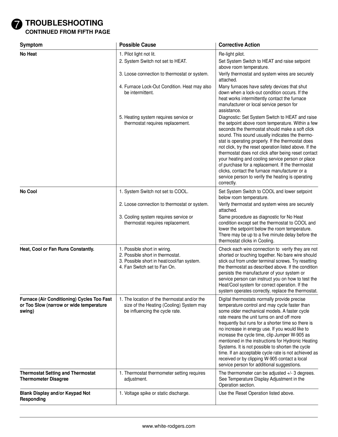
7 TROUBLESHOOTING
Reset Operation
If a voltage spike or static discharge blanks out the display or causes erratic thermostat operation you can reset the thermostat
by pressing ![]() and
and ![]() at the same time when system is switched from “OFF” to “HEAT” position. This also resets the factory defaults. If the thermostat has power, has been reset and
at the same time when system is switched from “OFF” to “HEAT” position. This also resets the factory defaults. If the thermostat has power, has been reset and
still does not function correctly contact your heating/cooling ser- vice person or place of purchase.
Batteries
For optimum performance, we recommend replacing batteries once a year with fresh “AAA” Energizer® alkaline batteries.
| Symptom | Possible Cause | Corrective Action | ||
| No Heat/No Cool/No Fan | 1. | Blown fuse or tripped circuit breaker. | Replace fuse or reset breaker. | |
| (common problems) | 2. | Furnace power switch to OFF. | Turn switch to ON. | |
|
| 3. | Furnace blower compartment door or | Replace door panel in proper position to engage | |
|
|
| panel loose or not properly installed. | safety interlock or door switch. | |
|
|
|
|
|
|
