3.Add the BTU/Hr of all fuel burning appliances in the space.
| _________________________BTU/Hr. | |||
Gas Water Heater* |
| _________________________BTU/Hr. | ||
Gas Furnace |
|
| _________________________BTU/Hr. | |
Vented Gas Heater |
| _________________________BTU/Hr. | ||
Gas Fireplace Logs |
| _________________________BTU/Hr. | ||
Other Gas Appliance* | +_________________________BTU/Hr. | |||
Total |
| = _________________________BTU/Hr. | ||
Example: | Gas water heater | 40000 BTU/Hr. | ||
| + | 18000 BTU/Hr. | ||
| Total |
| = | 58000 BTU/Hr. |
*Does not include
4.Compare the maximum BTU/Hr the space can support with the actual amount of BTU/Hr used.
| _____________BTU/Hr (maximum the space can support) | |
| _____________BTU/Hr (actual amount of BTU/Hr used) | |
Example: | 51200 | BTU/Hr (maximum the space can support) |
| 58000 | BTU/Hr (actual amount of BTU/Hr used) |
The space in the above example is a confined space because the actual BTU/Hr used is more than the maximum BTU/Hr the space can support. Additional fresh air must be provided. The following options are available.
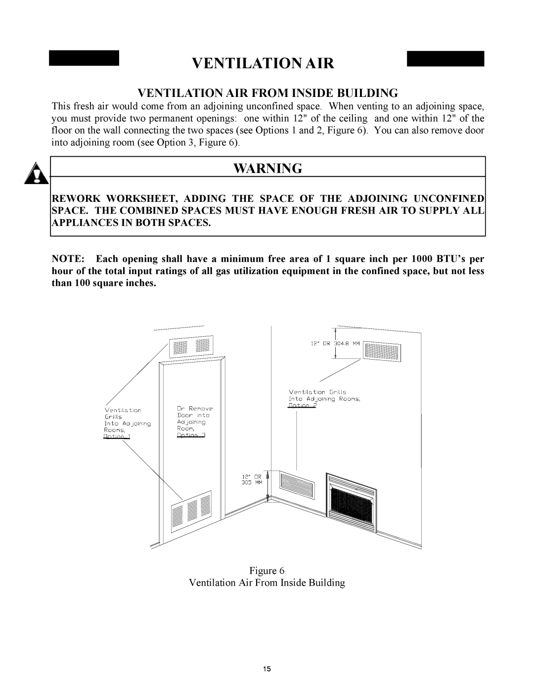
A.Rework worksheet, adding the space of an adjoining room. If the extra space provides an unconfined space, remove door to adjoining room or add ventilation grills between rooms. See “Ventilation Air From Inside Building”, page 15.
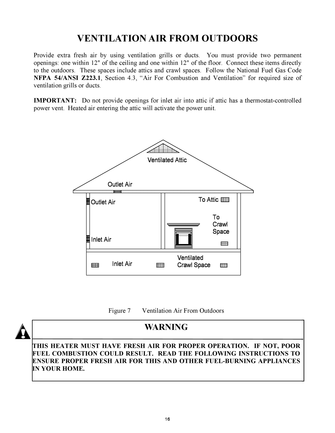
B.Vent room directly to the outdoors. See “Ventilation Air From Outdoors” page 16.
C.Install a lower BTU/Hr heater, if lower BTU/Hr size makes room unconfined.
If the actual BTU/Hr used is less than the maximum BTU/Hr the space can support, the space is unconfined. You will need no additional fresh air ventilation.
14
