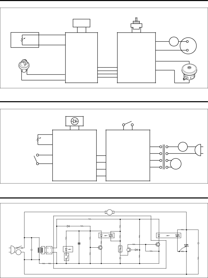
BLOCK DIAGRAM |
|
|
|
| ||
| LED PWB ASM | POWER S/W |
|
| ||
|
|
|
|
| ||
SLIDE VOLUME | BK | GY | BR | BR |
|
|
|
|
| ||||
|
|
|
|
| RD | T/P |
|
|
|
|
|
| |
HOSE |
|
|
|
| RD |
|
| SUB |
| MAIN |
|
| |
PRESSURE S/W |
|
|
|
| ||
| PWB |
| PWB | BL |
| |
|
| ASM |
| ASM |
| |
|
|
|
|
| ||
| GY |
|
|
| BL |
|
|
|
|
|
|
| |
| GY |
|
|
|
|
|
SCHEMATIC DIAGRAM |
|
|
| |||
LED PWB ASM
POWER S/W
BR BR
SLIDE VOLUME
|
|
|
| SUB |
|
|
| MAIN |
|
| T/P |
|
| |
| GY |
|
|
|
|
|
|
|
|
| ||||
|
| PWB |
|
|
| PWB |
|
|
|
|
| |||
PRESSURE S/W |
|
|
|
|
|
|
|
|
|
| ||||
|
| ASM |
|
|
| ASM |
|
|
|
|
| |||
| GY |
|
|
|
|
|
|
|
| M |
|
|
| |
|
|
|
|
|
|
|
|
|
|
|
|
|
| |
CIRCUIT DIAGRAM |
|
|
|
|
|
|
| |||||||
|
|
|
|
|
|
| MOTOR |
|
|
|
|
|
|
|
|
|
|
|
|
|
| M |
|
|
|
|
|
|
|
|
|
|
|
|
| R8 |
|
|
|
|
|
|
|
|
|
|
|
| D6 | R11 | 1K |
|
|
|
|
|
|
|
|
|
|
| 1N4002 | 390 |
|
| R9 |
|
|
|
|
|
| |
|
|
|
|
|
|
|
|
|
|
|
|
|
| |
|
|
|
|
|
|
|
| 100 |
|
|
|
|
|
|
|
|
|
|
|
|
| IC2 |
|
|
| IC1 | R3 |
|
|
|
|
|
|
|
|
|
| R15 |
| R6 |
| 470 |
|
|
|
|
| R16 |
|
| R12 |
|
|
| 1/2W |
|
| ||
|
|
|
|
| 12K |
| 18K |
|
| |||||
|
|
| 1.5K |
|
| 5.6K | R5 |
|
|
| ||||
POWER |
|
| + |
|
|
|
|
| C2 | |||||
|
|
|
|
| R14 |
| 100 |
|
|
| T2 | |||
S/W | TRANS | BD1 |
| LED1 | C4 |
| 100 | S/VOL |
|
|
| 0.1uF | ||
|
| Q2 |
| Q1 | G |
| ||||||||
|
|
|
|
| 2200uF |
| VR/ |
|
| 630V | ||||
|
|
|
|
| 16V | Q3 | A1015 |
| C3198 |
| T1 |
| ||
T/P | C1 |
|
|
|
| R13 | C3198 | 20K | D5 |
| R4 |
|
|
|
|
|
|
|
|
|
| R2 |
|
| |||||
| 0.47uF |
|
|
|
| 1K |
|
| 1N4148 | R7 |
|
| ||
|
|
| PRESSURE |
|
| 11K |
| R1 | ||||||
| /AC250 |
|
|
|
| C3 |
| 13K | 330 |
| ||||
|
|
|
| S/W |
|
|
|
|
| 1/2W |
| 100 | ||
|
|
|
|
|
|
| 0.47uF |
|
|
|
| |||
|
|
|
|
|
|
|
|
|
|
|
|
| 1/2W | |
|
|
|
|
|
|
|
| /100V |
|
|
|
|
| |
|
|
|
|
|
|
|
|
|
|
|
|
|
| |
| R1 |
|
|
|
|
|
|
|
|
|
|
|
| |
| 470K | 470K |
|
|
|
|
|
|
|
|
|
|
|
|
| 1/2W | 1/2W |
|
|
|
|
|
|
|
|
|
|
|
|
|
|
|
|
|
|
| 10 |
|
|
|
|
|
|
|