Seat Pan |
|
Battery Box | Label |
Door |
|
TO ROLL TRACTOR OFF SKID (See Operation section for location and function of controls)
• Press lift lever plunger and raise |
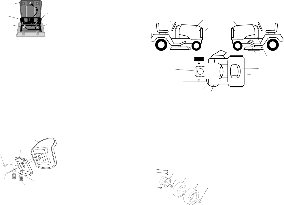
TRACTOR -- MODEL NUMBER 259723
DECALS
Terminal | Terminal |
INSTALL SEAT
Adjust seat before tightening adjustment knob.
•Remove adjustment bolt, lock washer and flat washer securing seat to cardboard packing and set aside for assembly of seat to tractor.
•Pivot seat upward and remove from the cardboard packing. Remove the cardboard packing and discard.
•Place seat on seat pan and assemble shoulder bolt. Tighten shoulder bolt securely.
•Assemble adjustment bolt, lock washer and flat washer loosely. Do not tighten.
•Lower seat into operating position and sit on seat.
•Slide seat until a comfortable position is reached which allows you to press clutch/brake pedal all the way down.
•Get off seat without moving its adjusted position.
•Raise seat and tighten adjustment knob securely.
Seat
| attachment lift lever to its highest |
| position. |
• | Release parking brake by depressing |
| clutch/brake pedal. |
• | Place gearshift lever in neutral (N) |
| position. |
• | Roll tractor forward off skid. |
• Remove banding holding discharge | |
| guard up against tractor. |
TO DRIVE TRACTOR OFF SKID (See Operation section for location and function of controls)
![]() WARNING: Before starting, read, understand and follow all instructions in the Operation section of this manual. Be sure tractor is in a
WARNING: Before starting, read, understand and follow all instructions in the Operation section of this manual. Be sure tractor is in a
• | Be sure all the above assembly steps |
| have been completed. |
• | Check engine oil level and fill fuel |
| tank with gasoline. |
• | Sit on seat in operating position, |
| depress clutch/brake pedal and set |
| the parking brake. |
• | Place gear shift lever in neutral (N) |
| position. |
• | Press lift lever plunger and raise |
| attachment lift lever to its highest |
| position. |
• | Start the engine. After engine has |
| started, move throttle control to idle |
| position. |
53
9 | 21 |
|
| 2 |
|
|
|
|
|
| 15 |
|
|
|
|
|
|
|
|
|
| |
|
|
|
|
|
| |
|
|
|
|
|
| |
|
|
|
|
|
| |
|
| 12 |
|
| ||
|
| 18 |
| |||
KEY | PART |
|
|
|
|
|
NO. | NO. | DESCRIPTION | ||||
1 | 156867 | Decal Oper P/L Eng | ||||
2 | ||||||
3 | 164578 | Decal Hood Rh | ||||
4 | 164579 | Decal Hood Lh | ||||
5 | 162398 | Decal Ins Strg Whl | ||||
8 | 164424 | Decal Panel Dash | ||||
9 | 171448 | Decal Fender Logo | ||||
10 | 145005 | Decal Battery Dngr/Psn | ||||
11 | 156439 | Decal Danger Fender | ||||
4
11
13
8
10
1
KEY | PART |
|
NO. | NO. | DESCRIPTION |
12 | 4900J | Decal Clutch/brake English |
15 | 136832 | Decal Mower Drive Schem 38 |
18 | 163128 | Decal Mower Enviro |
21 | 162392 | Decal Grille Logo |
- - | 138311 | Decal Lift Handle |
- - | 173487 | Manual Owners English |
- - | 173488 | Manual Owners Spanish |
Shoulder Seat Pan
Bolt
Adjustment | Flat Washer |
Bolt | Lock Washer |
NOTE: You may now roll or drive your tractor off the skid. Follow the appropriate instruction below to remove the tractor from the skid.
• | Depress clutch/brake pedal into full |
| “BRAKE” position and hold. Move |
| gearshift lever to 1st gear. |
• | Slowly release clutch/brake pedal and |
| slowly drive tractor off skid. |
• | Apply brake to stop tractor, set parking |
| brake and place gearshift lever in |
| neutral position. |
• | Turn ignition key to “OFF” position. |
Continue with the instructions that | |
follow. | |
WHEELS AND TIRES
|
|
| KEY | PART |
|
|
|
| NO. | NO. | DESCRIPTION |
|
|
| 1 | 59192 | Cap Value Tire |
|
|
| 2 | 65139 | Stem Value |
1 |
|
| 3 | 106222X | Tire F Ts 15 X 6 0 - 6 Service |
2 | 5,8 |
| 4 | 59904 | Tube Inner Front #35060 |
| 5 | 106732X427 | Rim Asm 6"front White | ||
| 4,10 |
| |||
|
|
|
| Service | |
| 7 |
| 6 | 278H | Fitting Grease |
|
|
| |||
| 3,9 |
| 7 | 9040H | Bearing Flange |
6 |
| 11 | 8 | 106108X427 | Rim Asm 8"rear White Service |
| 9 | 124635X | Tire R Ts 18x8 | ||
|
|
| |||
|
|
| 10 | 7152J | Tube Rear 9 5 X 8 Service |
|
|
| 11 | 104757X | Cap Axle Blk 1 50 X 1 00 |
|
|
| - - | 144334 | Sealant, Tire (10 oz. tube) |
NOTE: All component dimensions given in U. S. inches 1 inch = 25/4 mm
8 | 41 |