Dixon 966043101, SPDZTR 30 BF, 966064401 manual Torque Specifications, Metric Standard Hardware

Page 50

TECHNICAL DATA

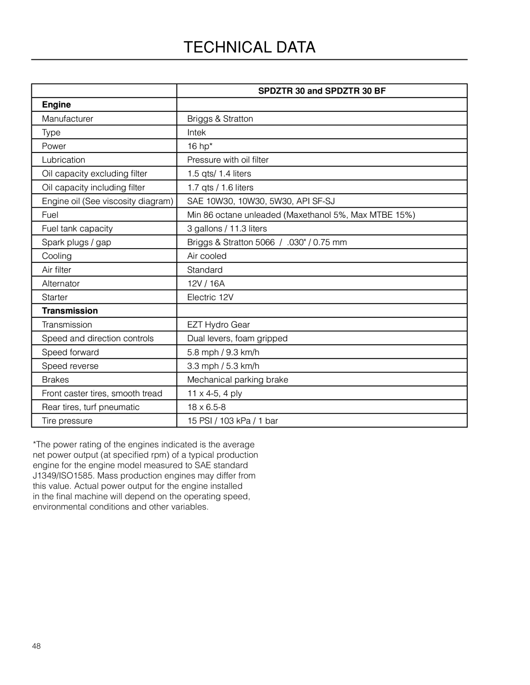
Torque Specifications

Engine crankshaft bolt

50 ft/lb (67 Nm)

Standard ¼" fasteners

9 ft/lb (12 Nm)

Deck pulley bolts

150 ft/lb (203 Nm)

Standard 5/16" fasteners

18 ft/lb (25 Nm)

Lug nuts

75 ft/lb (100 Nm)

Standard 3/8" fasteners

33 ft/lb (44 Nm)

Blade bolt

90 ft/lb (122 Nm)

Standard 7/16" fasteners

52 ft/lb (70 Nm)


Standard ½” fasteners

80 ft/lb (110 Nm)

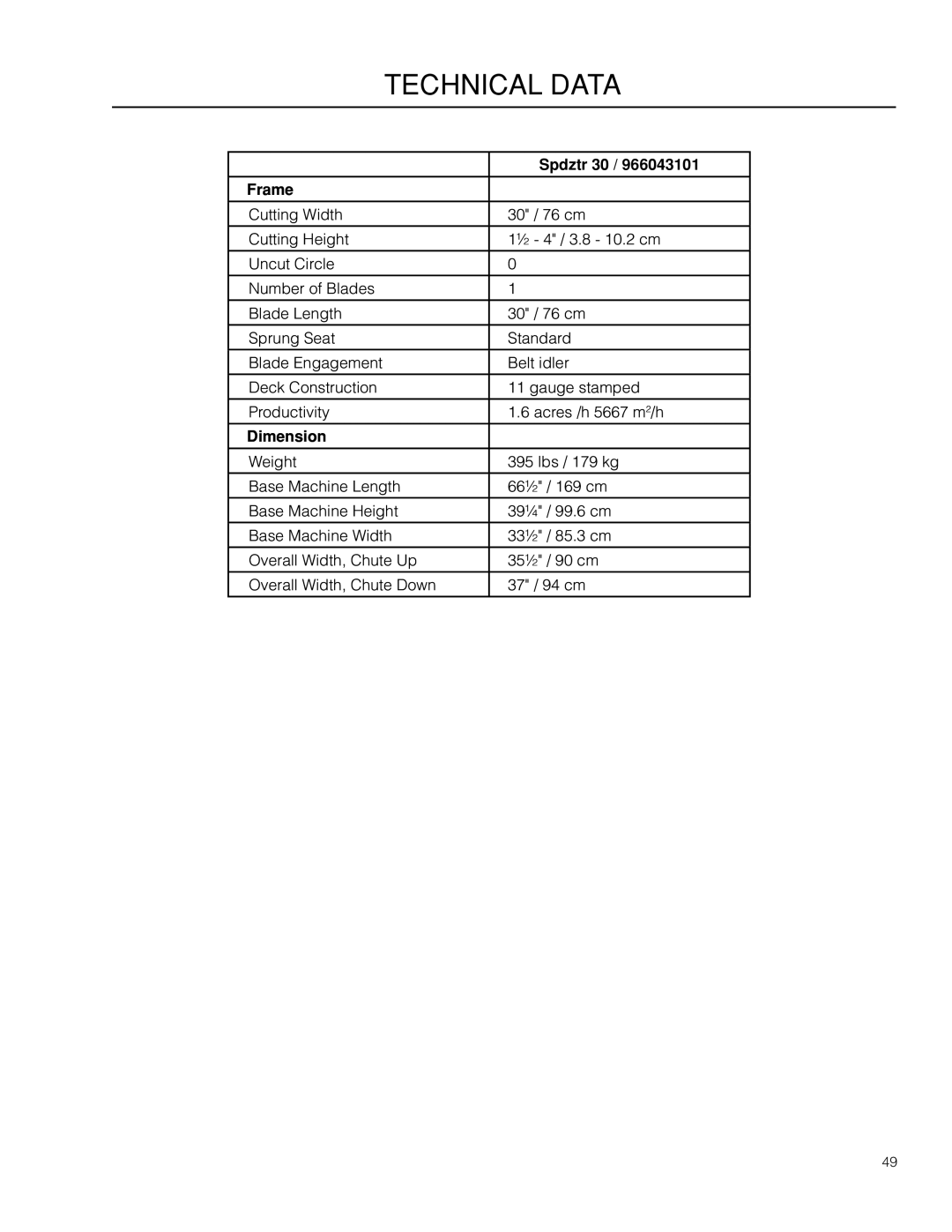
HEX HEAD CAP SCREWS

Shank Size (Diameter in inches, fine or coarse thread)

The torque values shown should be used as a general guideline when specific torque values are not given.

U.S. Standard Hardware


Grade


SAE Grade 5


SAE Grade 8

Flangelock Screw


w/Flangelock Nut


ft./lbs


ft./lbs


Nm

ft./lbs


Nm

ft./lbs


Nm


¼


9


12

13


18


5/16


18


24

28


38

24


33


3/8


31


42

46


62

40


54


7/16


50


68

75


108


½


75


102

115


156


9/16


110


150

165


224


5/8


150


203

225


305


¾


250


339

370


502


7/8


378


513

591


801


11/8


782


1060

1410


1912


** Grade 5 - Minimum commercial quality (lower quality not recommended)

Shank Size (Diameter in inches, fine or coarse thread)

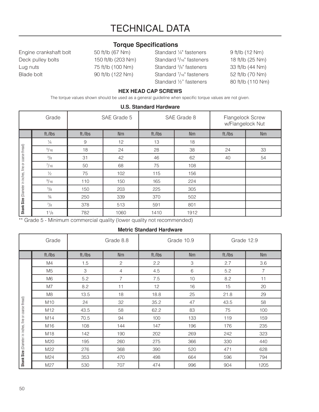
Metric Standard Hardware


Grade


Grade 8.8


Grade 10.9

Grade 12.9


ft./lbs


ft./lbs


Nm

ft./lbs


Nm

ft./lbs


Nm


M4


1.5


2

2.2


3

2.7


3.6


M5


3


4

4.5


6

5.2


7


M6


5.2


7

7.5


10

8.2


11


M7


8.2


11

12


16

15


20


M8


13.5


18

18.8


25

21.8


29


M10


24


32

35.2


47

43.5


58


M12


43.5


58

62.2


83

75


100


M14


70.5


94

100


133

119


159


M16


108


144

147


196

176


235


M18


142


190

202


269

242


323


M20


195


260

275


366

330


440


M22


276


368

390


520

471


628


M24


353


470

498


664

596


794


M27


530


707

474


996

904


1205


50

Image 50
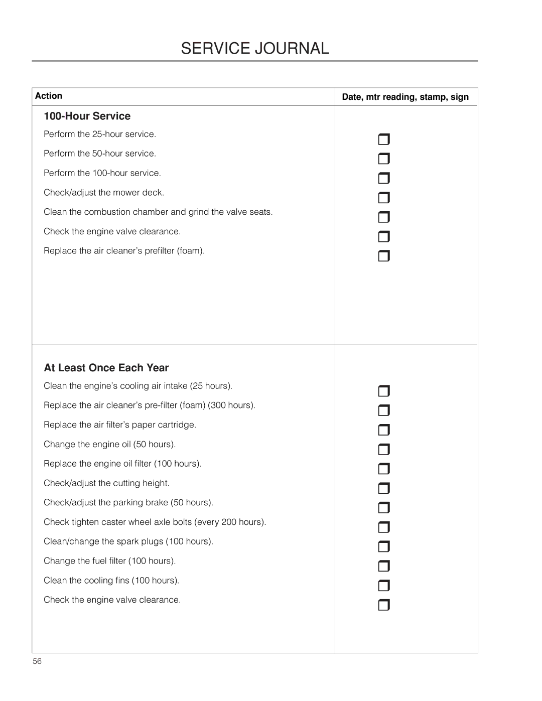
Contents Operator Manual Page Contents Page Introduction Good Service Manufacturing NumberSymbols and decals Remove key before Safety General OperationNever take passengers Personal Safety Equipment Slope OperationChildren Safe Handling of Gasoline General Maintenance Never make adjustments with the engine running Transport Controls Control LocationsSteering Control Levers Throttle Control Ignition SwitchParking Brake Choke Control RefuelingTracking Fuel Shut Off ValveMower Deck Lifting Lever Always use the high position F to transportBlade Control Lever Manual TransportTraining SteeringBefore Starting Starting the EnginePlace controls in neutral position Open the fuel valve To remove cables, reverse order Weak BatteryJumper cables Running Operating on Hills Mowing Tips Stopping the Engine Manual Transport Maintenance Maintenance ScheduleBefore Always use protective glasses when handling the battery BatteryTo clean battery and terminals Safety System Ignition SystemTire Pressures Engine Filters and MaintenanceEngine Cooling Air Intake To replace deck belt BeltsDeck Belt EZT Belt Cutting BladesAdjusting the Mower Deck Leveling deckUse protective glasses when cleaning and washing Cleaning and WashingRemoval and installation of caster wheel Caster WheelsLubrication GeneralDeck spindle Front Wheel MountFront Wheel Bearings Troubleshooting Problem CauseTroubleshooting Service Winter StorageSchematics Engine Technical DataSpdztr 30 and Spdztr 30 BF TransmissionFrame DimensionSpdztr 30 Metric Standard Hardware Torque SpecificationsStandard Hardware USA requirements CE requirementsWarranty Dixon ZTR ResidentialAction Date, mtr reading, stamp, sign Service JournalDelivery Service Hour Service After the First 5-8 HoursService Journal At Least Once Each Year Service Journal Service Journal Page 115 161527R2 09/25/09

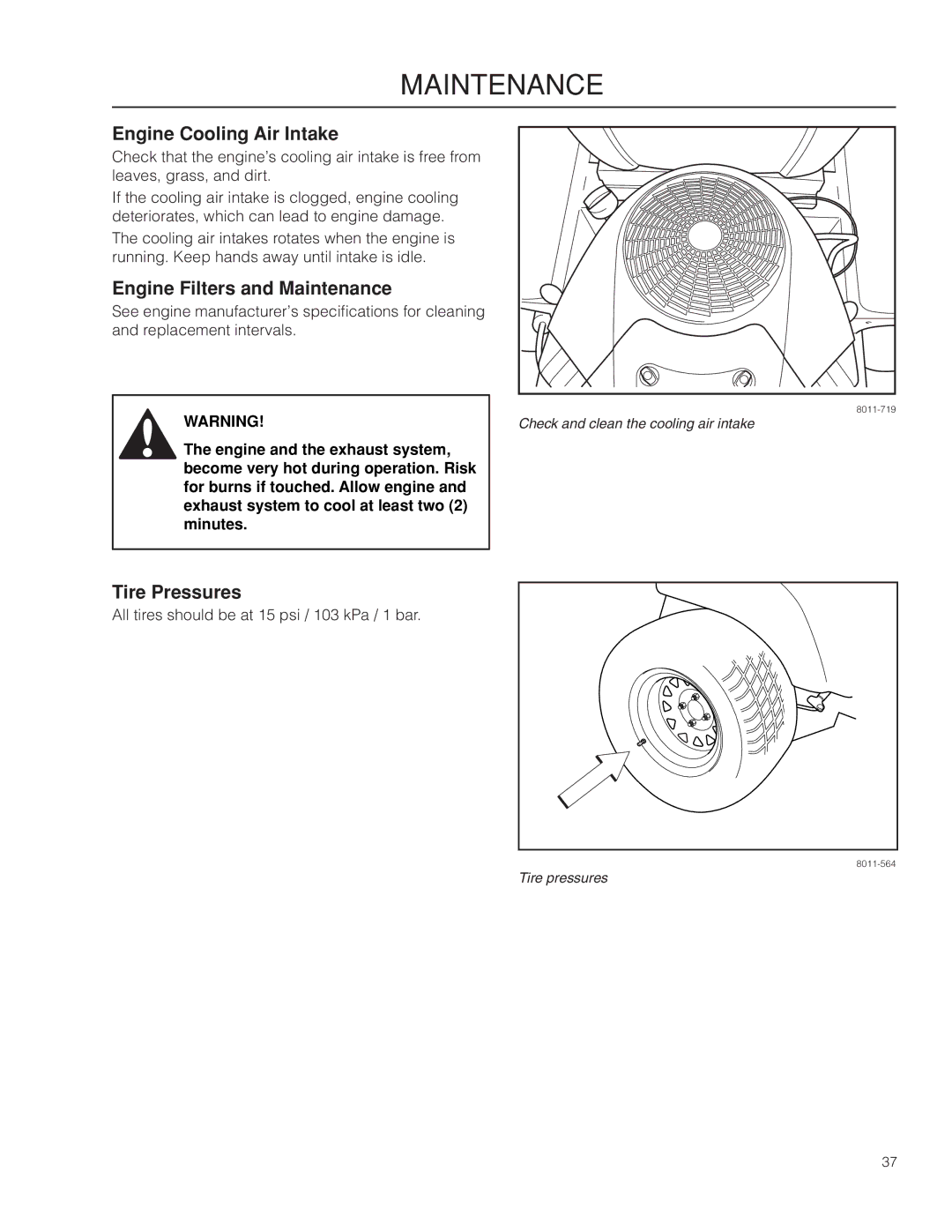
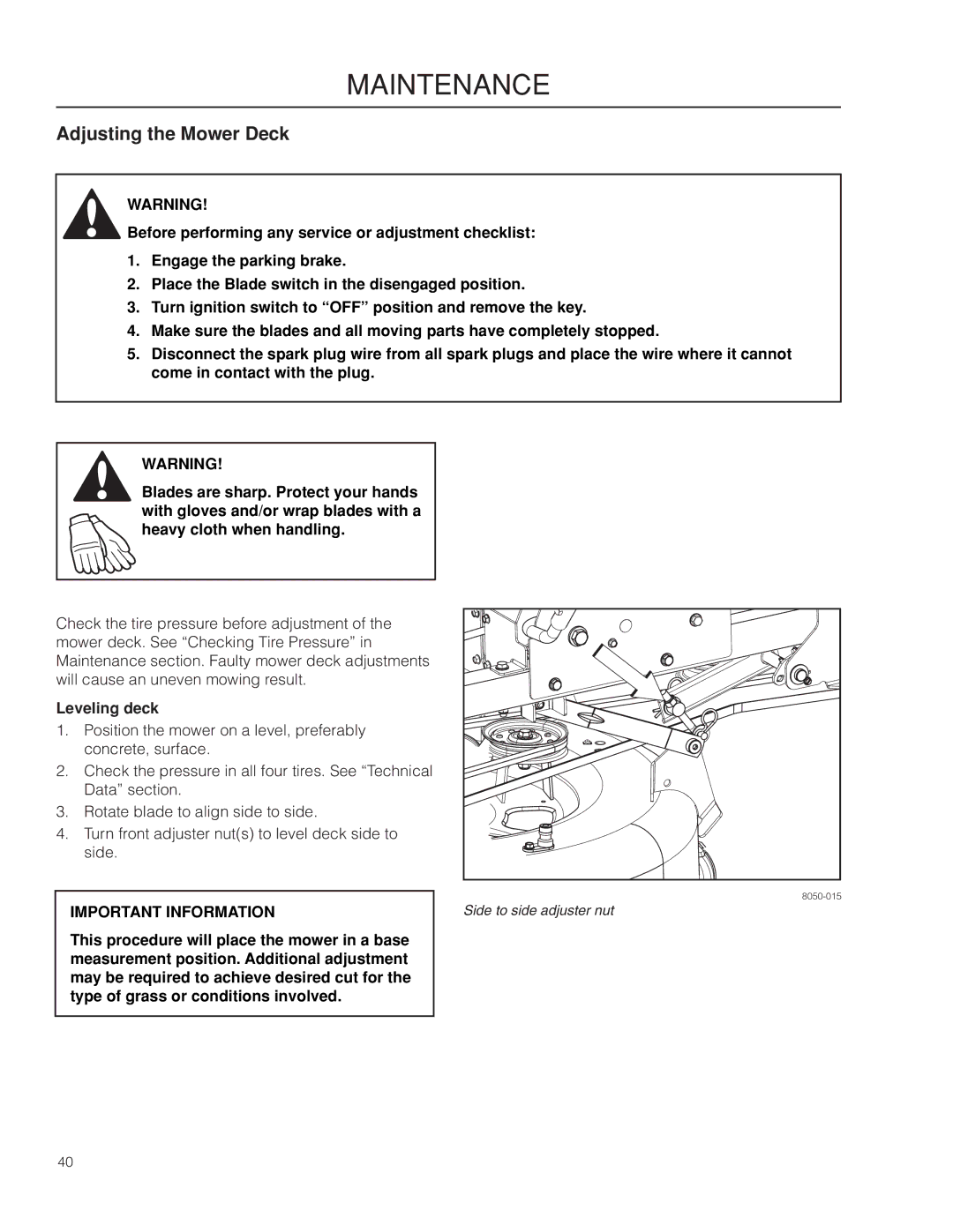
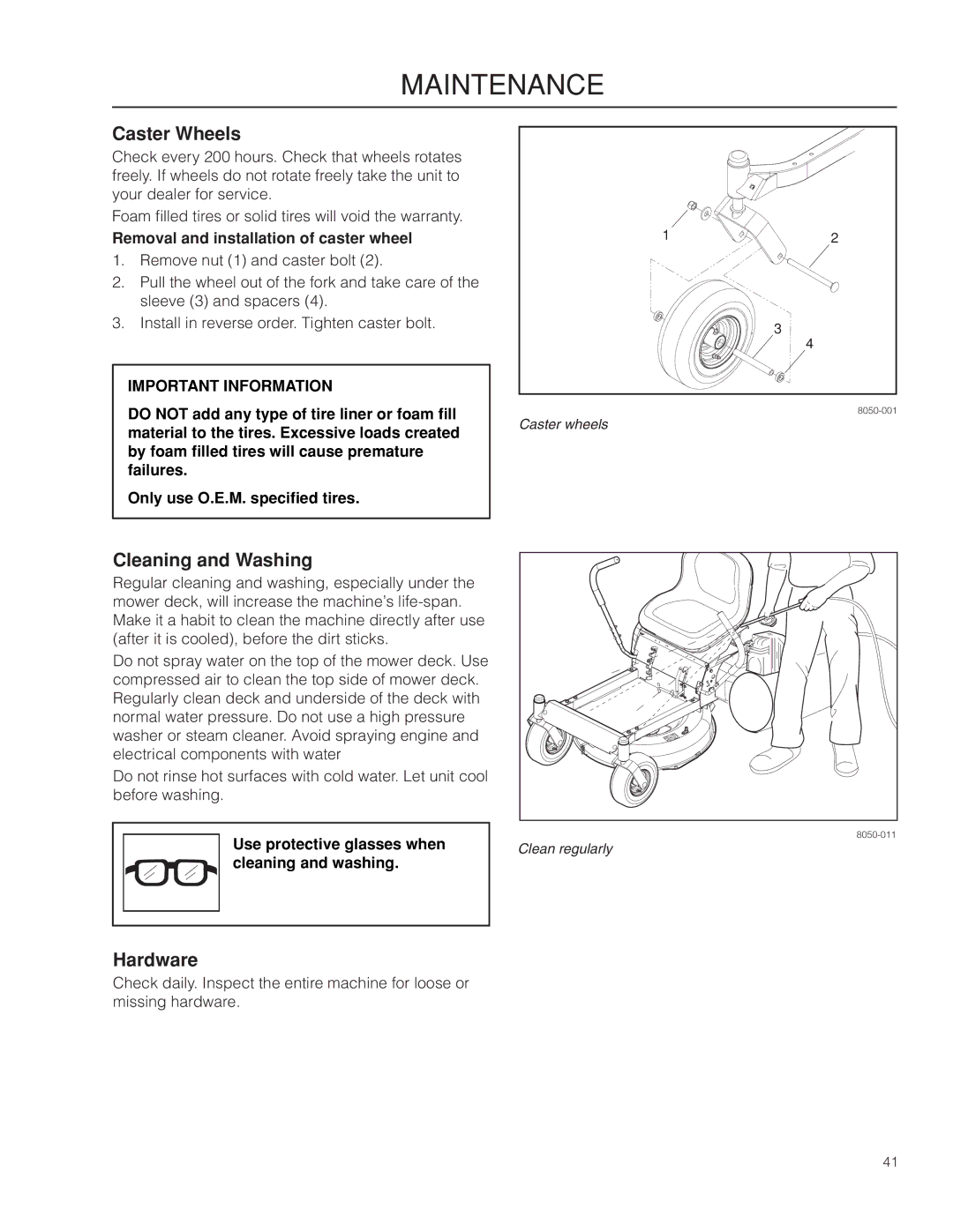
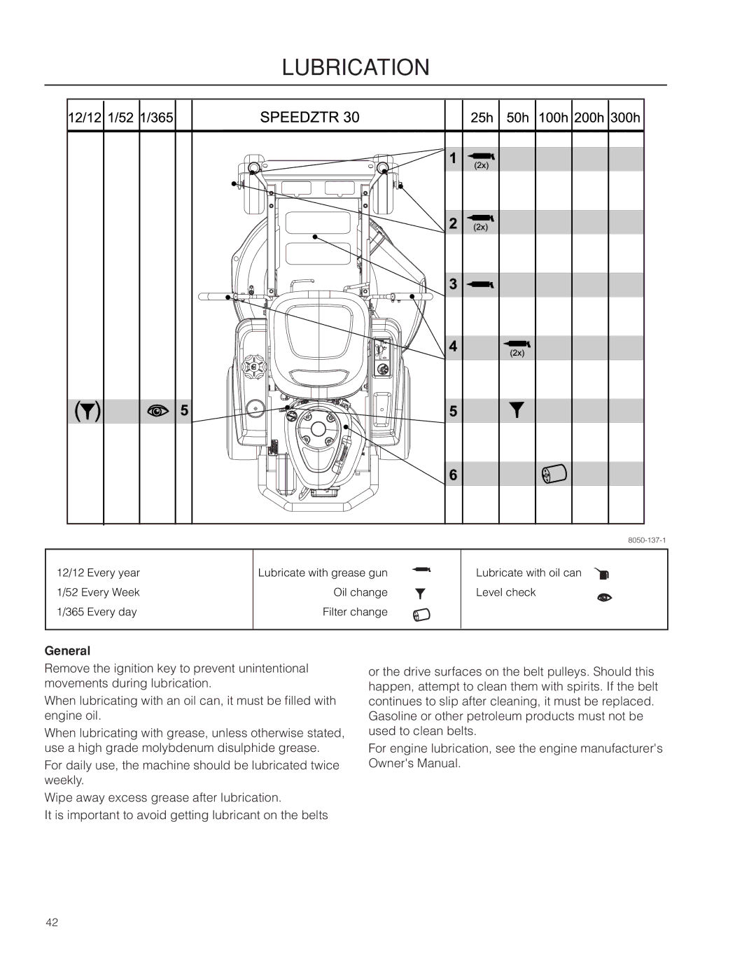
966064401, 966043101, SPDZTR 30, SPDZTR 30 BF specifications

The Dixon SPDZTR 30,966064401, and SPDZTR 30 BF,966043101 are cutting-edge tools designed for professionals seeking reliability and efficiency in their operations. These models combine advanced engineering with robust design, making them ideal for various industries, including construction, manufacturing, and utilities.

One of the main features of the Dixon SPDZTR series is its durability. Constructed from high-quality materials, these tools can withstand harsh working conditions, thus ensuring longevity and consistent performance. The bodies are designed to resist corrosion, wear, and impact, making them suitable for outdoor and industrial environments.

Another key characteristic of the SPDZTR models is their ergonomic design. The handles are crafted for comfort, allowing for extended use without causing fatigue. This feature is crucial for professionals who rely on their tools for long hours, as it helps reduce strain and enhances productivity.

The SPDZTR 30,966064401, in particular, boasts advanced technology that incorporates precision engineering. This model features a unique locking mechanism that ensures secure connections, preventing leaks or disconnections during operation. This technology is vital for maintaining the efficiency of fluid transfer systems, where reliability is paramount.

On the other hand, the SPDZTR 30 BF,966043101 is designed with versatility in mind. It is compatible with various attachments and accessories, allowing users to customize their tools based on specific tasks. This adaptability makes the SPDZTR 30 BF a favorite among professionals who deal with multiple applications.

Additionally, both models prioritize safety. They feature integrated safety mechanisms that mitigate the risk of accidental disconnections or malfunctions, ensuring safe operation at all times. This commitment to safety aligns with industry standards, making the SPDZTR series a trustworthy choice.

In conclusion, the Dixon SPDZTR 30,966064401, and SPDZTR 30 BF,966043101 are exemplary tools that combine durability, ergonomic design, advanced technology, and safety features. Their robust construction and adaptability make them essential for professionals in various fields, ultimately enhancing productivity and ensuring reliability in demanding environments. Investing in these tools means investing in quality and performance that lasts.