Husqvarna YT1942T owner manual Steering Assembly

Page 29

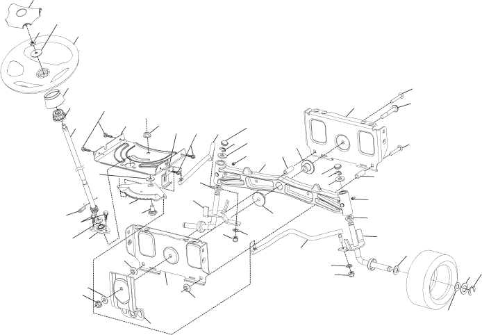
TRACTOR - - MODEL NUMBER YT1942T (96043000300), PRODUCT NO. 960 43 00-03

STEERING ASSEMBLY

26

45

511

20


21

63


16

19

60


57

63


59


6


35


4


58


64


28


13

22


50


69

65

68

50


steering-tex_1-vgt

70


54


65

66


61

9


8

7

67

54


3

55


2


9 8

55


7


3


67

6


15

14


5


62

13


14


8


15

53


13


KEY

PART


NO.

NO.

DESCRIPTION

1532 19 39-43 Wheel, Steering

2532 19 59-68 Axle Asm., Front

3

532 18 32-26 Fitting, Grease

4532 19 47-43 Spindle Asm., LH

5532 19 47-44 Spindle Asm., RH

6532 12 49-31 Bearing, Race Thrust Harden

7532 12 17-48 Washer 25/32 x 1-5/8 x 16 Ga.

8812 00 00-29 Ring, Klip #T5304-75

9

532 12 12-32 Cap, Spindle

13532 12 17-49 Washer 25/32 x 1-1/4 x 16 Ga.

14810 04 06-00 Washer, Lock Hvy Hlcl Spr 3/8

15873 54 06-00 Nut, Crown Lock 3/8-24 unf

16

532 19 47-46

Shaft Steering

19

532 19 47-29

Plate Steering

20

532 40 29-60

Boot, Steering

21532 18 67-37 Adapter, Wheel Steering

22532 19 48-45 Bushing, Strg. Blk

26

532 19 36-52 Insert, Wheel Steering

28

817 00 06-12 Screw 3/8-16 x 3/4

35

532 19 47-32

Gear, Sector Plate

45

819 11 38-12

Washer 11/32 ID x 2-3/8 x 12 Ga.

48

817 06 06-12

Screw 3/8-16 x .75

50

873 90 06-00

Nut Lock 3/8-16 unc

KEY

PART


NO.

NO.

DESCRIPTION

51

873 94 08-00 Nut Hex Jam Toplock 1/2-20 unf

53532 18 89-67 Washer Hardened

.793 x 1.637 x .060

54874 76 06-36 Bolt Hex 3/8-16 unc x 2-1/4

55532 19 76-36 Spacer Brace Axle

57

532 19 72-46 Bracket Upstop

58532 19 47-47 Bolt Shoulder Sector Pivot CFM

59532 19 47-48 Washer Thrust Sector Steering

60873 97 10-00 Nut Flange Lock 5/8-11

61

532 19 47-40

Draglink LH

62

532 19 47-41

Draglink, RH

63817 00 05-12 Screw 5/16-18 x 3/4

64532 19 98-49 Retainer Clip Spring Steering

65532 19 47-34 Brace Axle Front

66871 02 07-48 Bolt Hex Fghd 7/16-14 x 3 Serr

67532 19 47-37 Bushing PM Front Axle

68873 90 07-00 Nut Lock Flange 7/16-14 Gr. 5

69532 19 91-62 Washer 1.5 x .505 x .118

70532 19 61-97 Bracket Deck Susp. Front

NOTE: All component dimensions given in U.S. inches 1 inch = 25.4 mm

29

Image 29
Contents YT1942T Safe Operation Practices for Ride-On Mowers Safety RulesGeneral Operation II. Slope OperationIV. Towing ServiceIII. Children Table of Contents Contents of Hardware Pack Check Deck Levelness Check Tire PressureCheck for Proper Position of ALL Belts Check Brake SystemOperation Know Your Tractor To SET Parking Brake See Fig HOW to USE Your TractorStopping See Figs To USE Throttle Control D See FigTo Move Forward and Backward See Fig To Adjust Mower Cutting Height See FigBefore Starting the Engine To Start Engine See Fig Mowing TipsLubrication Chart MaintenanceBlade Removal See Fig BatteryTractor Engine To Remove Mower See Fig Service and AdjustmentsCleaning Slide mower out from under right side of tractor To Install Mower See FigsTo Level Mower To Replace Motion Drive Belt See Fig To Replace Mower Drive Belt See FigTo Check Brake To Remove Wheel for Repairs See Fig To Start Engine with a Weak Battery See FigFront Wheel TOE-IN/CAMBER To Adjust Choke Control To Adjust Throttle Control CableTo Adjust Carburetor To Replace Headlight BulbOther StorageFuel System Engine OILTroubleshooting Points Engine dies when Tractor - Model Number YT1942T 96043000300, Product no 43 SchematicElectrical KEY Part Description Chassis Steering Assembly 155 DriveTransaxle, Peerless Spark Arrester KIT Engine532 19 Shaft Asm., Lift Mower Lift532 19 Seat Seat AssemblyWheels and Tires DecalsMower Deck Mower Deck Warranty Statement Suggested Guide for Sighting Slopes for Safe Operation 532 40 19-72 Rev 05.24.06 TR/VB/TR