INTERCONNECTING TWO SWITCHES
Interconnecting Two Switches
To interconnect two Switches, you will need the XRN Interconnect Module Kit (part number 3C17715). This kit contains:
Two XRN Interconnect Modules (3C17716)
One standard XRN Interconnect Cable (3C17721)
You can interconnect two Switch units that are located in
!separate racks with a 5 m (16.40 ft) long Interconnect cable (3C17722). Contact your network supplier for further information.
CAUTION: It is important that you only plug an XRN
!Interconnect Cable (3C17721 or 3C17722) into the connector on the XRN Interconnect Module (3C17716).
Connecting any other
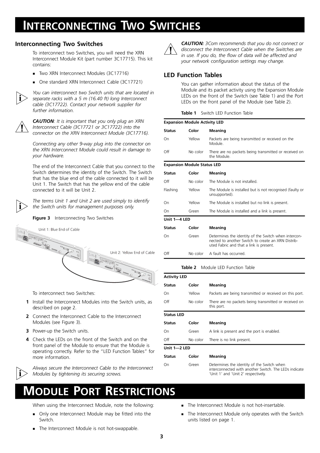
The end of the Interconnect Cable that you connect to the Switch determines the identity of the Switch. The Switch that has the blue end of the cable connected to it will be Unit 1. The Switch that has the yellow end of the cable connected to it will be Unit 2.
The terms Unit 1 and Unit 2 are used simply to identify
!the Switch units for management purposes only.
Figure 3 Interconnecting Two Switches
Unit 1: Blue End of Cable
CAUTION: 3Com recommends that you do not connect or
!disconnect the Interconnect Cable when the Switches are in use. If you do, the flow of data will be affected and your network configuration settings may change.
LED Function Tables
You can gather information about the status of the Module and its packet activity using the Expansion Module LEDs on the front of the Switch (see Table 1) and the Port LEDs on the front panel of the Module (see Table 2).
Table 1 Switch LED Function Table
Expansion Module Activity LED
Status | Color | Meaning |
On | Yellow | Packets are being transmitted or received on the |
|
| Module. |
Off | No color | There are no packets being transmitted or received on |
|
| the Module. |
| ||
Expansion Module Status LED | ||
Status | Color | Meaning |
Off | No color | The Module is not installed. |
Flashing | Yellow | The Module is installed but is not recognised (faulty or |
|
| unsupported). |
On | Yellow | The Module is installed but no link is present. |
On | Green | The Module is installed and a link is present. |
|
| |
Unit |
| |
Status | Color | Meaning |
90 | VSUPPLY- | DATA |
|
|
- 240 | Hz | A | I | |
|
|
|
|
INPUT |
|
V | A |
27 | 12Max |
(max)Console |
|
19200,8,1,N | S/N: X |
| XXX/7XXXXXXXXX |
Unit 1 |
|
U | Activity |
nit 2 | |
| Status |
3 | C17716 XRN |
|
|
| Interconnect |
| |
|
| Module | |
|
|
|
Unit 2: Yellow End of Cable
| S |
|
|
|
90 |
|
| ||
- 240 | Hz | A | I | |
|
|
|
| |
INPUT |
|
V | A |
27 | 12Max |
(max)Console |
|
| Unit 1 |
|
19200,8,1,N | S/N: X | XXX/7XXXXXXXXX | Unit 2 | Activity |
|
|
| Status |
3 | C17716 XRN |
|
|
| Interconnect |
| |
|
| Module | |
|
|
|
On | Green | Determines the identity of the Switch when intercon- |
|
| nected to another Switch to create an XRN Distrib- |
|
| uted Fabric and that a link is present. |
Off | No color | A fault has occurred. |
|
|
|
Table 2 Module LED Function Table
Activity LED
To interconnect two Switches:
1Install the Interconnect Modules into the Switch units, as described on page 2.
2Connect the Interconnect Cable to the Interconnect Modules (see Figure 3).
3
4Check the LEDs on the front of the Switch and on the front panel of the Module to ensure that the Module is operating correctly. Refer to the “LED Function Tables” for more information.
Always secure the Interconnect Cable to the Interconnect
!Modules by tightening its securing screws.
Status | Color | Meaning |
On | Yellow | Packets are being transmitted or received on this port. |
Off | No color | There are no packets being transmitted or received on |
|
| this port. |
|
|
|
Status LED |
|
|
Status | Color | Meaning |
On | Green | A link is present and the port is enabled. |
Off | No color | There is no link present. |
|
| |
Unit |
| |
Status | Color | Meaning |
On | Green | Determines the identity of the Switch when |
|
| interconnected with another Switch. The LEDs indicate |
|
| ‘Unit 1’ and ‘Unit 2’ respectively. |
MODULE PORT RESTRICTIONS
When using the Interconnect Module, note the following:
Only one Interconnect Module may be fitted into the Switch.
The Interconnect Module is not
The Interconnect Module is not
The Interconnect Module only operates with the Switch units listed on page 1.
3