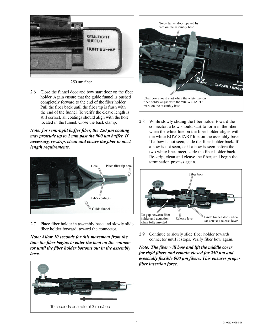
250/900 specifications
3M 250/900 is a high-performance adhesive transfer tape that has become a preferred choice for various industries due to its advanced technology and exceptional bonding qualities. This product is a double-sided tape that features a strong acrylic adhesive on both sides, making it ideal for applications requiring high initial tack and long-term adhesion.One of the main features of 3M 250/900 is its versatility. It adheres well to a wide range of substrates including metal, glass, and various plastics. This makes it suitable for use in diverse applications such as automotive assembly, sign-making, and electronic device manufacturing. The tape’s ability to bond different materials together translates to enhanced design possibilities, providing manufacturers with the flexibility they need to innovate.
3M's patented technology is another hallmark of the 250/900 tape. The product incorporates a unique chemical formulation that enhances its performance under various environmental conditions. It exhibits excellent temperature resistance, ensuring that bonds remain intact even in extreme heat or cold. Furthermore, the adhesive is resistant to solvents and moisture, making it ideal for applications that may come into contact with harsh chemicals or humidity.
The 3M 250/900 tape is also known for its ease of use. It features a liner that allows for simple application, reducing the potential for errors during installation. The tape can be die-cut into custom shapes and sizes, which adds to its convenience for manufacturers requiring specific configurations for their projects. The release liner ensures that the adhesive remains protected until use, allowing for long-term storage and handling without compromising the product's integrity.
Another notable characteristic of the 3M 250/900 is its transparency. This feature is particularly beneficial in applications where aesthetics are important, such as in displays or decorative items. The clear adhesive allows for discreet bonding that does not detract from the overall appearance of the product being assembled.
In summary, the 3M 250/900 adhesive transfer tape stands out in the market due to its strong adhesion properties, versatility, ease of use, and advanced technology. Whether for industrial applications or DIY projects, the reliability and performance of this tape make it a go-to solution for many professionals seeking a durable bonding option.

