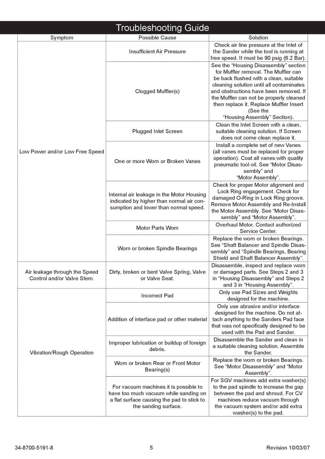
Troubleshooting Guide
Symptom | Possible Cause | Solution | |
|
| Check air line pressure at the Inlet of | |
| Insufficient Air Pressure | the Sander while the tool is running at | |
|
| free speed. It must be 90 psig (6.2 Bar). | |
|
| See the “Housing Disassembly” section | |
|
| for Muffler removal. The Muffler can | |
|
| be back flushed with a clean, suitable | |
|
| cleaning solution until all contaminates | |
| Clogged Muffler(s) | and obstructions have been removed. If | |
|
| the Muffler can not be properly cleaned | |
|
| then replace it. Replace Muffler Insert | |
|
| (See the | |
|
| “Housing Assembly” Section). | |
|
| Clean the Inlet Screen with a clean, | |
| Plugged Inlet Screen | suitable cleaning solution. If Screen | |
|
| does not come clean replace it. | |
|
| Install a complete set of new Vanes | |
Low Power and/or Low Free Speed |
| (all vanes must be replaced for proper | |
| One or more Worn or Broken Vanes | operation). Coat all vanes with quality | |
| pneumatic tool oil. See “Motor Disas- | ||
|
| ||
|
| sembly” and | |
|
| “Motor Assembly”. | |
|
| Check for proper Motor alignment and | |
| Internal air leakage in the Motor Housing | Lock Ring engagement. Check for | |
| damaged | ||
| indicated by higher than normal air con- | ||
| Remove Motor Assembly and | ||
| sumption and lower than normal speed. | ||
| the Motor Assembly. See “Motor Disas- | ||
|
| ||
|
| sembly” and “Motor Assembly”. | |
| Motor Parts Worn | Overhaul Motor. Contact authorized | |
| Service Center. | ||
|
| ||
|
| Replace the worn or broken Bearings. | |
| Worn or broken Spindle Bearings | See “Shaft Balancer and Spindle Disas- | |
| sembly” and “Spindle Bearings, Bearing | ||
|
| ||
|
| Shield and Shaft Balancer Assembly”. | |
|
| Disassemble, inspect and replace worn | |
Air leakage through the Speed | Dirty, broken or bent Valve Spring, Valve | or damaged parts. See Steps 2 and 3 | |
Control and/or Valve Stem. | or Valve Seat. | in “Housing Disassembly” and Steps 2 | |
|
| and 3 in “Housing Assembly”. | |
| Incorrect Pad | Only use Pad Sizes and Weights | |
| designed for the machine. | ||
|
| ||
|
| Only use abrasive and/or interface | |
|
| designed for the machine. Do not at- | |
| Addition of interface pad or other material | tach anything to the Sanders Pad face | |
|
| that was not specifically designed to be | |
|
| used with the Pad and Sander. | |
| Improper lubrication or buildup of foreign | Disassemble the Sander and clean in | |
| a suitable cleaning solution. Assemble | ||
| debris. | ||
Vibration/Rough Operation | the Sander. | ||
| |||
| Worn or broken Rear or Front Motor | Replace the worn or broken Bearings. | |
| See “Motor Disassembly” and “Motor | ||
| Bearing(s) | ||
| Assembly”. | ||
|
| ||
|
| For SGV machines add extra washer(s) | |
| For vacuum machines it is possible to | to the pad spindle to increase the gap | |
| have too much vacuum while sanding on | between the pad and shroud. For CV | |
| a flat surface causing the pad to stick to | machines reduce vacuum through | |
| the sanding surface. | the vacuum system and/or add extra | |
|
| washer(s) to the pad. |
Revision 10/03/07 |