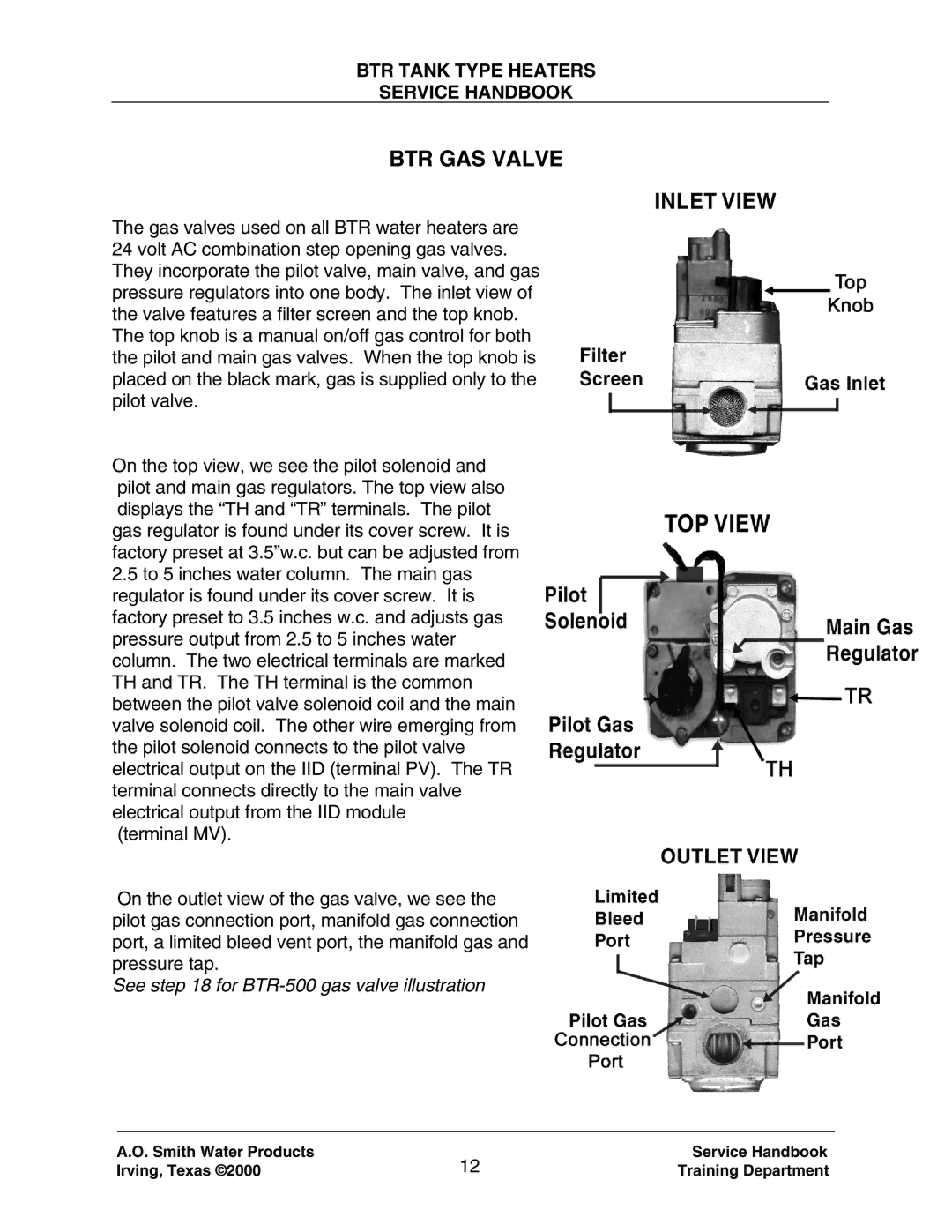
120 trough 500 specifications
A.O. Smith, a renowned leader in water heating solutions, offers a wide range of products tailored to meet diverse needs. Among its most significant offerings is the A.O. Smith 120 through 500 series, which includes various models designed for both residential and commercial applications.One of the standout features of the A.O. Smith 120 through 500 series is its efficiency. Many models are designed with advanced thermal insulation and heating technologies, which significantly minimize energy loss. This efficiency not only benefits the environment but also helps users save on energy bills, making these water heaters an economical choice for both homeowners and businesses.
The series includes both gas and electric water heaters, allowing users to select the option that best fits their energy preferences and availability. Gas models typically offer faster heating times and are ideal in areas where natural gas is readily accessible. Conversely, electric models come with a variety of voltage options, accommodating different electrical setups and preferences.
A notable technological advancement in the A.O. Smith 120 through 500 series is the incorporation of smart connectivity options. Some models are equipped with Wi-Fi capabilities, allowing users to monitor and control their water heater remotely via mobile apps. This feature provides real-time data, alerts, and updates, ensuring that users have complete control over their water heating needs.
Moreover, durability is a hallmark of the A.O. Smith brand. The tanks are often constructed from high-quality materials designed to resist corrosion. Many models also feature glass lining and protective coatings, which enhance the lifespan of the heater and minimize the risk of leaks.
Safety is another priority for A.O. Smith. The series is equipped with various safety features such as automatic shut-off mechanisms and temperature controls, ensuring that any potential issues are promptly addressed.
Overall, the A.O. Smith 120 through 500 series encapsulates innovation, efficiency, and reliability. With its versatile offerings and advanced features, it stands as an excellent choice for anyone in need of a dependable water heating solution. Whether for home use or in a commercial setting, these models deliver consistent performance and peace of mind.

