
BTI - 65, BTI - 85 specifications
A.O. Smith is a leader in water heating solutions with a formidable reputation built over more than 140 years. Among its offerings are the BTI-85 and BTI-65 commercial water heaters, engineered to deliver exceptional performance for diverse applications, ranging from foodservice to industrial processes.The A.O. Smith BTI series is recognized for its robust design and advanced features. The BTI-85, with an 85-gallon capacity, and the BTI-65, featuring a 65-gallon capacity, are crafted to meet high-demand situations while ensuring energy efficiency. These units are equipped with a high-efficiency gas burner, ensuring quick recovery rates, which is essential for operations requiring large volumes of hot water in a short period.
One of the standout technologies in the BTI series is the ceramic-lined tank. This design not only helps prevent corrosion but also extends the life of the water heater. Additionally, both the BTI-85 and BTI-65 feature a foam insulation layer that minimizes heat loss, optimizing energy usage and contributing to lower operational costs.
Another significant characteristic of these units is the user-friendly control system. The digital thermostat offers precise temperature control, allowing users to set and maintain the desired water temperature efficiently, which is crucial in environments where temperature consistency is key. Furthermore, the BTI series is equipped with advanced safety features, such as a flame rollout switch and high-temperature limit switch, ensuring safe operation under various conditions.
A.O. Smith has also incorporated ease of maintenance into the design of the BTI models. The anode rod and sacrificial anode are easily accessible, facilitating routine checks and replacements to prolong tank life. The units also feature a removable cleanout for sediment control, which helps in maintaining heater efficiency over time.
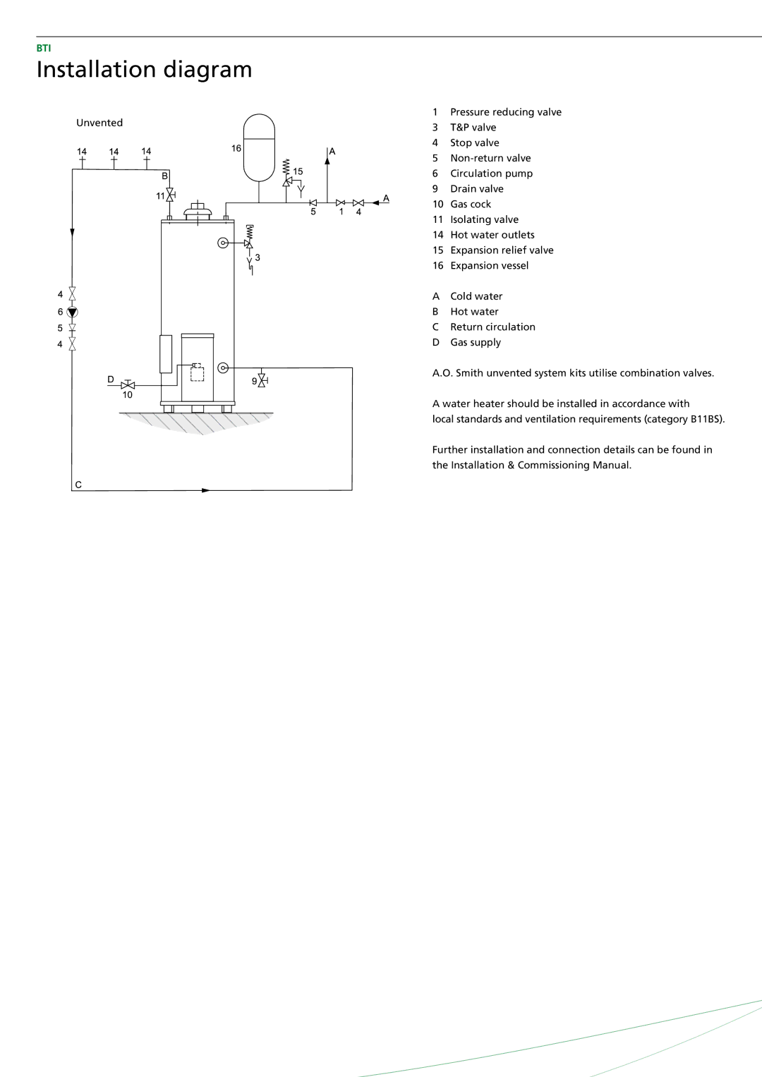
In terms of installation, the BTI-85 and BTI-65 models are designed to fit into various spaces, thanks to their compact dimensions. These water heaters can be vented in multiple configurations, providing flexibility to meet building codes and installation requirements.
Overall, A.O. Smith's BTI-85 and BTI-65 models offer a perfect blend of efficiency, durable construction, and smart technology, making them ideal choices for businesses looking for reliable water heating solutions. With a commitment to innovation and customer satisfaction, A.O. Smith continues to set the standard in the water heating industry.