|
|
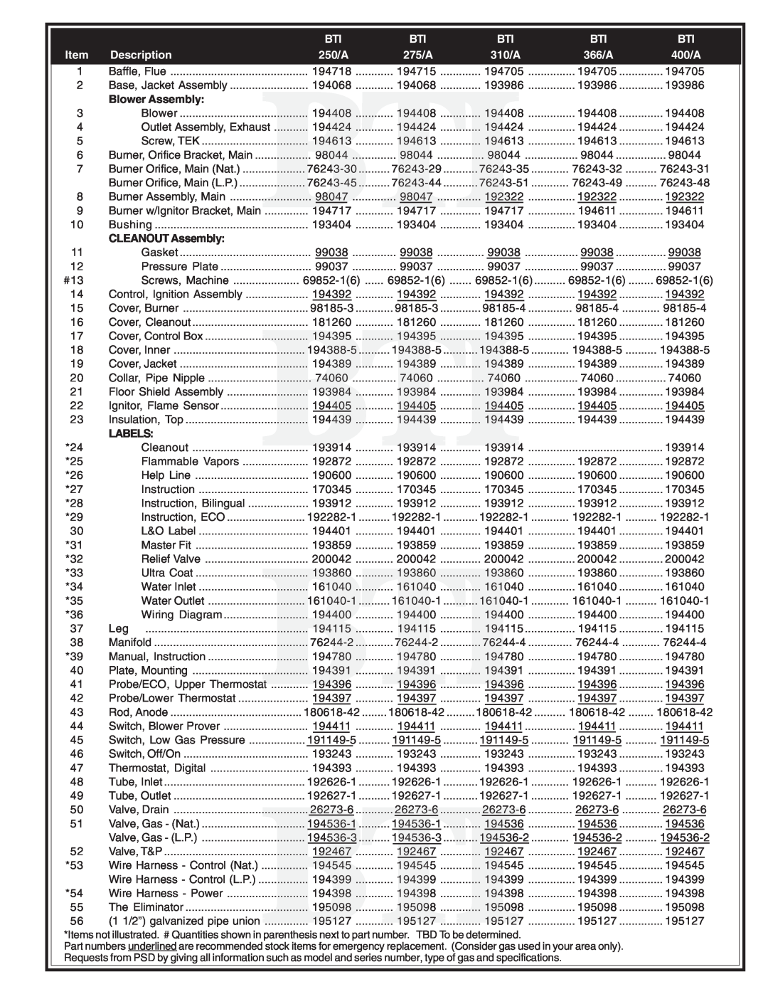
| BTI | BTI | BTI | BTI | BTI |
Item | Description |
| 250/A | 275/A | 310/A | 366/A | 400/A |
1 | Baffle, Flue | 194718 | 194715 | 194705 | 194705 | 194705 | |
2 | Base, Jacket Assembly | 194068 | 194068 | 193986 | 193986 | 193986 | |
| Blower Assembly: |
|
|
|
|
|
|
3 | Blower | 194408 | 194408 | 194408 | 194408 | 194408 | |
4 | Outlet Assembly, Exhaust | ........... 194424 | 194424 | 194424 | 194424 | 194424 | |
5 | Screw, TEK | 194613 | 194613 | 194613 | 194613 | 194613 | |
6 | Burner, Orifice Bracket, Main | 98044 | 98044 | 98044 | 98044 | 98044 | |
7 | Burner Orifice, Main (Nat.) | ||||||
| Burner Orifice, Main (L.P.) | ||||||
8 | Burner Assembly, Main | 98047 | 98047 | 192322 | 192322 | 192322 | |
9 | Burner w/Ignitor Bracket, Main | 194717 | 194717 | 194717 | 194611 | 194611 | |
10 | Bushing | 193404 | 193404 | 193404 | 193404 | 193404 | |
|
|
| |||||
| CLEANOUT Assembly: |
|
|
|
|
|
|
11 | Gasket | 99038 | 99038 | 99038 | 99038 | 99038 | |
12 | Pressure Plate | 99037 | 99037 | 99037 | 99037 | 99037 | |
#13 | Screws, Machine | ||||||
14 | Control, Ignition Assembly | 194392 | 194392 | 194392 | 194392 | 194392 | |
15 | Cover, Burner | ||||||
16 | Cover, Cleanout | 181260 | 181260 | 181260 | 181260 | 181260 | |
17 | Cover, Control Box | 194395 | 194395 | 194395 | 194395 | 194395 | |
18 | Cover, Inner | ||||||
19 | Cover, Jacket | 194389 | 194389 | 194389 | 194389 | 194389 | |
20 | Collar, Pipe Nipple | 74060 | 74060 | 74060 | 74060 | 74060 | |
21 | Floor Shield Assembly | 193984 | 193984 | 193984 | 193984 | 193984 | |
22 | Ignitor, Flame Sensor | 194405 | 194405 | 194405 | 194405 | 194405 | |
23 | Insulation, Top | 194439 | 194439 | 194439 | 194439 | 194439 | |
| LABELS: |
|
|
|
|
|
|
*24 | Cleanout | 193914 | 193914 | 193914 | 192872 | 193914 | |
*25 | Flammable Vapors | 192872 | 192872 | 192872 | 192872 | ||
|
|
| |||||
*26 | Help Line | 190600 | 190600 | 190600 | 190600 | 190600 | |
*27 | Instruction | 170345 | 170345 | 170345 | 170345 | 170345 | |
*28 | Instruction, Bilingual | 193912 | 193912 | 193912 | 193912 | 193912 | |
*29 | Instruction, ECO | ||||||
30 | L&O Label | 194401 | 194401 | 194401 | 194401 | 194401 | |
*31 | Master Fit | 193859 | 193859 | 193859 | 193859 | 193859 | |
*32 | Relief Valve | 200042 | 200042 | 200042 | 200042 | 200042 | |
*33 | Ultra Coat | 193860 | 193860 | 193860 | 193860 | 193860 | |
*34 | Water Inlet | 161040 | 161040 | 161040 | 161040 | 161040 | |
*35 | Water Outlet | ||||||
*36 | Wiring Diagram | 194400 | 194400 | 194400 | 194400 | 194400 | |
37 | Leg | 194115 | 194115 | 194115 | 194115 | 194115 | |
38 | Manifold | ||||||
*39 | Manual, Instruction | 194780 | 194780 | 194780 | 194780 | 194780 | |
40 | Plate, Mounting | 194391 | 194391 | 194391 | 194391 | 194391 | |
41 | Probe/ECO, Upper Thermostat | 194396 | 194396 | 194396 | 194396 | 194396 | |
42 | Probe/Lower Thermostat | 194397 | 194397 | 194397 | 194397 | 194397 | |
|
|
| |||||
43 | Rod, Anode | ||||||
44 | Switch, Blower Prover | 194411 | 194411 | 194411 | 194411 | 194411 | |
45 | Switch, Low Gas Pressure | ||||||
46 | Switch, Off/On | 193243 | 193243 | 193243 | 193243 | 193243 | |
47 | Thermostat, Digital | 194393 | 194393 | 194393 | 194393 | 194393 | |
48 | Tube, Inlet | ||||||
49 | Tube, Outlet | ||||||
50 | Valve, Drain | ||||||
51 | Valve, Gas - (Nat.) | 194536 | 194536 | 194536 | |||
| Valve, Gas - (L.P.) | ||||||
52 | Valve, T&P | 192467 | 192467 | 192467 | 192467 | 192467 | |
*53 | Wire Harness - Control (Nat.) | ............... | 194545 | 194545 | 194545 | 194545 | 194545 |
| Wire Harness - Control (L.P.) | 194399 | 194399 | 194399 | 194399 | 194399 | |
*54 | Wire Harness - Power | 194398 | 194398 | 194398 | 194398 | 194398 | |
55 | The Eliminator | 195098 | 195098 | 195098 | 195098 | 195098 | |
56 |
| .............. | 195127 | 195127 | 195127 | 195127 | 195127 |
| (1 1/2”) galvanized pipe unionBTI |
|
| ||||
*Items not illustrated. # Quantities shown in parenthesis next to part number. TBD To be determined.
Part numbers underlined are recommended stock items for emergency replacement. (Consider gas used in your area only). Requests from PSD by giving all information such as model and series number, type of gas and specifications.