Table of Contents
Section 1: Assembly and
Land Pride
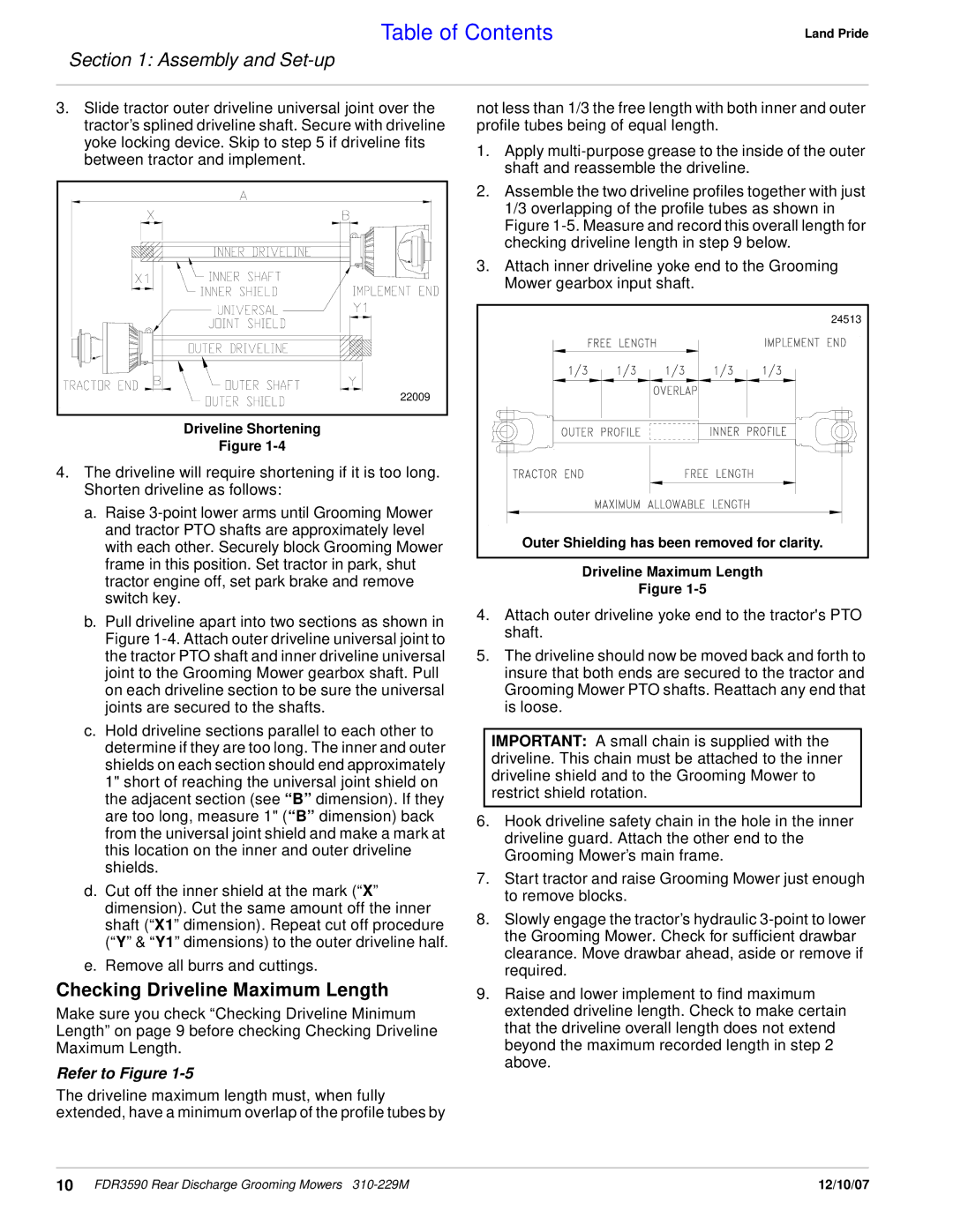
3.Slide tractor outer driveline universal joint over the tractor’s splined driveline shaft. Secure with driveline yoke locking device. Skip to step 5 if driveline fits between tractor and implement.
22009 |
Driveline Shortening
Figure
4.The driveline will require shortening if it is too long. Shorten driveline as follows:
a.Raise
b.Pull driveline apart into two sections as shown in Figure
c.Hold driveline sections parallel to each other to determine if they are too long. The inner and outer shields on each section should end approximately 1" short of reaching the universal joint shield on the adjacent section (see “B” dimension). If they are too long, measure 1" (“B” dimension) back from the universal joint shield and make a mark at this location on the inner and outer driveline shields.
d.Cut off the inner shield at the mark (“X” dimension). Cut the same amount off the inner shaft (“X1” dimension). Repeat cut off procedure (“Y” & “Y1” dimensions) to the outer driveline half.
e.Remove all burrs and cuttings.
Checking Driveline Maximum Length
Make sure you check “Checking Driveline Minimum Length” on page 9 before checking Checking Driveline Maximum Length.
Refer to Figure 1-5
The driveline maximum length must, when fully extended, have a minimum overlap of the profile tubes by
not less than 1/3 the free length with both inner and outer profile tubes being of equal length.
1.Apply
2.Assemble the two driveline profiles together with just 1/3 overlapping of the profile tubes as shown in Figure
3.Attach inner driveline yoke end to the Grooming Mower gearbox input shaft.
24513
Outer Shielding has been removed for clarity.
Driveline Maximum Length
Figure
4.Attach outer driveline yoke end to the tractor's PTO shaft.
5.The driveline should now be moved back and forth to insure that both ends are secured to the tractor and Grooming Mower PTO shafts. Reattach any end that is loose.
IMPORTANT: A small chain is supplied with the driveline. This chain must be attached to the inner driveline shield and to the Grooming Mower to restrict shield rotation.
6.Hook driveline safety chain in the hole in the inner driveline guard. Attach the other end to the Grooming Mower’s main frame.
7.Start tractor and raise Grooming Mower just enough to remove blocks.
8.Slowly engage the tractor’s hydraulic
9.Raise and lower implement to find maximum extended driveline length. Check to make certain that the driveline overall length does not extend beyond the maximum recorded length in step 2 above.
10 FDR3590 Rear Discharge Grooming Mowers | 12/10/07 |