ELECTRICAL

General

Check the water heater model and rating plate information against the characteristics of the branch circuit electrical supply. Do not connect the heater to an improper source of electricity.

Voltage applied to the heater should not vary more than +5% to -10% of the model and rating plate marking for satisfactory operation.

Do NOT energize the branch circuit for any reason before the water heater tank is filled with water. Doing so may cause the heating elements to fail.

The factory wiring is attached to a terminal block on the unit. The branch circuit is connected to the block through an opening provided on the heater. Factory terminal block has 500 MCM maximum copper wire size capacity in each opening. If apparent field wire size is over 500 MCM multiple terminal blocks will be furnished. If other opening sizes are desired they should be specified when unit is ordered.

The installation must conform to these instructions and the local code authority having jurisdiction. Grounding and electrical wiring connected to the water heater must also conform to the National Electrical Code, NFPA 70. This publication is available from The National Fire Protection Association, 1 Batterymarch Park, Quincy, MA 02269.

Branch Circuit

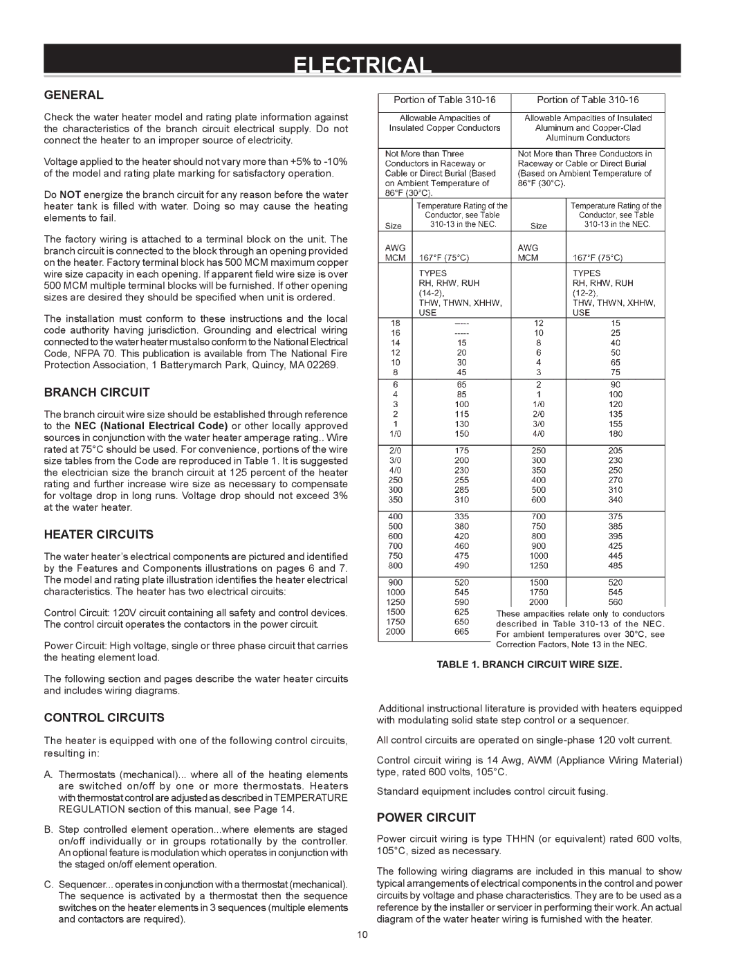
The branch circuit wire size should be established through reference to the NEC (National Electrical Code) or other locally approved sources in conjunction with the water heater amperage rating.. Wire rated at 75°C should be used. For convenience, portions of the wire size tables from the Code are reproduced in Table 1. It is suggested the electrician size the branch circuit at 125 percent of the heater rating and further increase wire size as necessary to compensate for voltage drop in long runs. Voltage drop should not exceed 3% at the water heater.

Heater Circuits

The water heater’s electrical components are pictured and identified by the Features and Components illustrations on pages 6 and 7. The model and rating plate illustration identifies the heater electrical characteristics. The heater has two electrical circuits:

Control Circuit: 120V circuit containing all safety and control devices. The control circuit operates the contactors in the power circuit.

Power Circuit: High voltage, single or three phase circuit that carries the heating element load.

The following section and pages describe the water heater circuits and includes wiring diagrams.

Control Circuits

The heater is equipped with one of the following control circuits, resulting in:

A. Thermostats (mechanical)... where all of the heating elements are switched on/off by one or more thermostats. Heaters with thermostat control are adjusted as described in TEMPERATURE REGULATION section of this manual, see Page 14.

B. Step controlled element operation...where elements are staged on/off individually or in groups rotationally by the controller. An optional feature is modulation which operates in conjunction with the staged on/off element operation.

C.Sequencer... operates in conjunction with a thermostat (mechanical). The sequence is activated by a thermostat then the sequence switches on the heater elements in 3 sequences (multiple elements and contactors are required).

These ampacities relate only to conductors described in Table 310-13 of the NEC. For ambient temperatures over 30°C, see Correction Factors, Note 13 in the NEC.

TABLE 1. BRANCH CIRCUIT WIRE SIZE.

Additional instructional literature is provided with heaters equipped with modulating solid state step control or a sequencer.

All control circuits are operated on single-phase 120 volt current.

Control circuit wiring is 14 Awg, AWM (Appliance Wiring Material) type, rated 600 volts, 105°C.

Standard equipment includes control circuit fusing.

Power Circuit

Power circuit wiring is type THHN (or equivalent) rated 600 volts, 105°C, sized as necessary.

The following wiring diagrams are included in this manual to show typical arrangements of electrical components in the control and power circuits by voltage and phase characteristics. They are to be used as a reference by the installer or servicer in performing their work. An actual diagram of the water heater wiring is furnished with the heater.

10

Page 10
Image 10
A.O. Smith DVE-150, DHE-200 instruction manual Electrical, Branch Circuit, Heater Circuits, Control Circuits, Power Circuit

DVE-150, DHE-200 specifications

A.O. Smith has established itself as a leading brand in the water heating industry, and its DVE-150 and DHE-200 models showcase the company's commitment to efficiency and innovation. Both units are designed to cater to residential and commercial water heating needs, offering a range of features that enhance performance and reliability.

The DVE-150 is a high-efficiency electric water heater that boasts a 150-gallon capacity. It is ideal for larger households or small commercial applications where hot water demand is significant. One of the standout features of the DVE-150 is its advanced heating element technology. This model uses high-density insulation that reduces heat loss, ensuring more effective energy use. The unit operates at a high recovery rate, allowing it to provide consistent hot water quickly, even during peak usage times.

On the other hand, the DHE-200 is a gas water heater, equipped with a 200-gallon capacity. This model is ideal for high-demand environments where large volumes of hot water are required. The DHE-200 incorporates an innovative direct vent system that enhances efficiency and safety by removing combustion gases from the living space. The modulating gas burner further ensures that the unit operates at optimal efficiency, adjusting the heat output based on the demand for hot water.

Both models feature an intuitive digital display that allows users to monitor and adjust their settings easily. Additionally, they come with advanced diagnostic tools that provide real-time feedback on the system's performance, making maintenance easier and more efficient.

Safety is a top concern for A.O. Smith, and both the DVE-150 and DHE-200 are designed with multiple safety features. These include high-temperature limit switches, pressure relief valves, and flame rollout switches, all of which work to protect the unit from potential hazards.

In terms of installation, both models offer flexible options. They are designed to fit in various spaces, accommodating different installation environments. This versatility is essential for both new constructions and retrofitting older systems.

The DVE-150 and DHE-200 are also backed by A.O. Smith's industry-leading warranty, providing customers with peace of mind regarding their investment. Overall, these models embody A.O. Smith's dedication to quality, efficiency, and safety, making them excellent choices for those in need of reliable water heating solutions.