GPS-75 specifications
The A.O. Smith GPS-75 is a state-of-the-art gas water heater designed to deliver efficient and reliable hot water solutions to residential and light commercial users. With its sleek design and advanced technology, this unit stands out in the competitive water heating market.One of the primary features of the GPS-75 is its impressive 75-gallon capacity, making it ideal for larger households or businesses that require a substantial volume of hot water. This water heater delivers a first-hour rating of up to 91 gallons, ensuring that you will always have enough hot water on demand, even during peak usage times.
The GPS-75 utilizes a high-efficiency gas burner that operates at an energy factor of 0.67, which helps to minimize energy costs while providing robust heating performance. This means that users can enjoy powerful hot water output without having to worry about skyrocketing energy bills. Additionally, the unit is equipped with a state-of-the-art electronic ignition system that ensures reliable startup and operation. This feature eliminates the need for a pilot light, enhancing safety and energy efficiency.
In terms of durability, the GPS-75 features a glass-lined interior which protects the tank from rust and corrosion. This adds to the unit's longevity and reduces the need for maintenance and replacement. The water heater also comes with insulating foam in the tank and a special temperature and pressure relief valve to enhance safety.
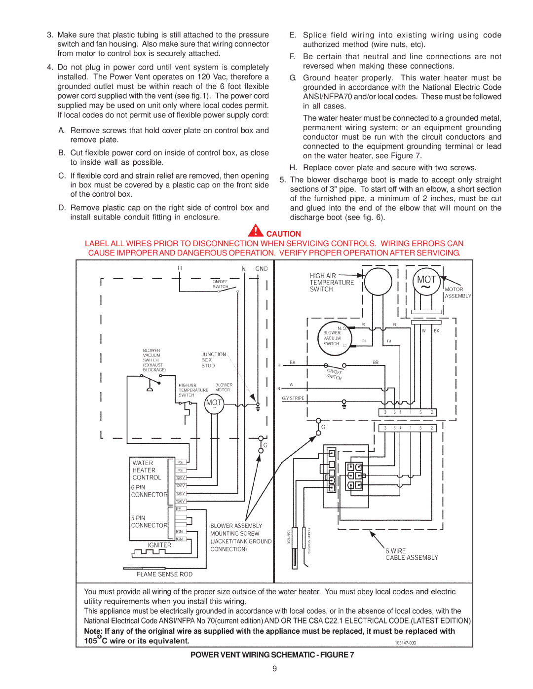
Another notable technology included in the GPS-75 is its advanced diagnostics feature. This system is designed to monitor and diagnose problems, allowing for quick troubleshooting and minimizing downtime. This is especially useful for service professionals and homeowners alike, as it facilitates efficient maintenance and reduces unexpected repair costs.
The GPS-75 also has an environmentally friendly design, meeting stringent energy efficiency guidelines. This aligns with the growing demand for sustainable solutions in modern homes and businesses.
In summary, the A.O. Smith GPS-75 gas water heater combines an impressive 75-gallon capacity, high efficiency, and advanced safety features to offer users a reliable and economical hot water solution. With its innovative technologies and durable construction, it stands as a strong contender in the water heating industry. Whether for residential or commercial use, the GPS-75 ensures that hot water is always available when needed.

