for the openings that provide fresh air into confined spaces only. Do not refer to these illustrations for the purpose of vent installation. See Venting Installation on page 18 for complete venting installation instructions.

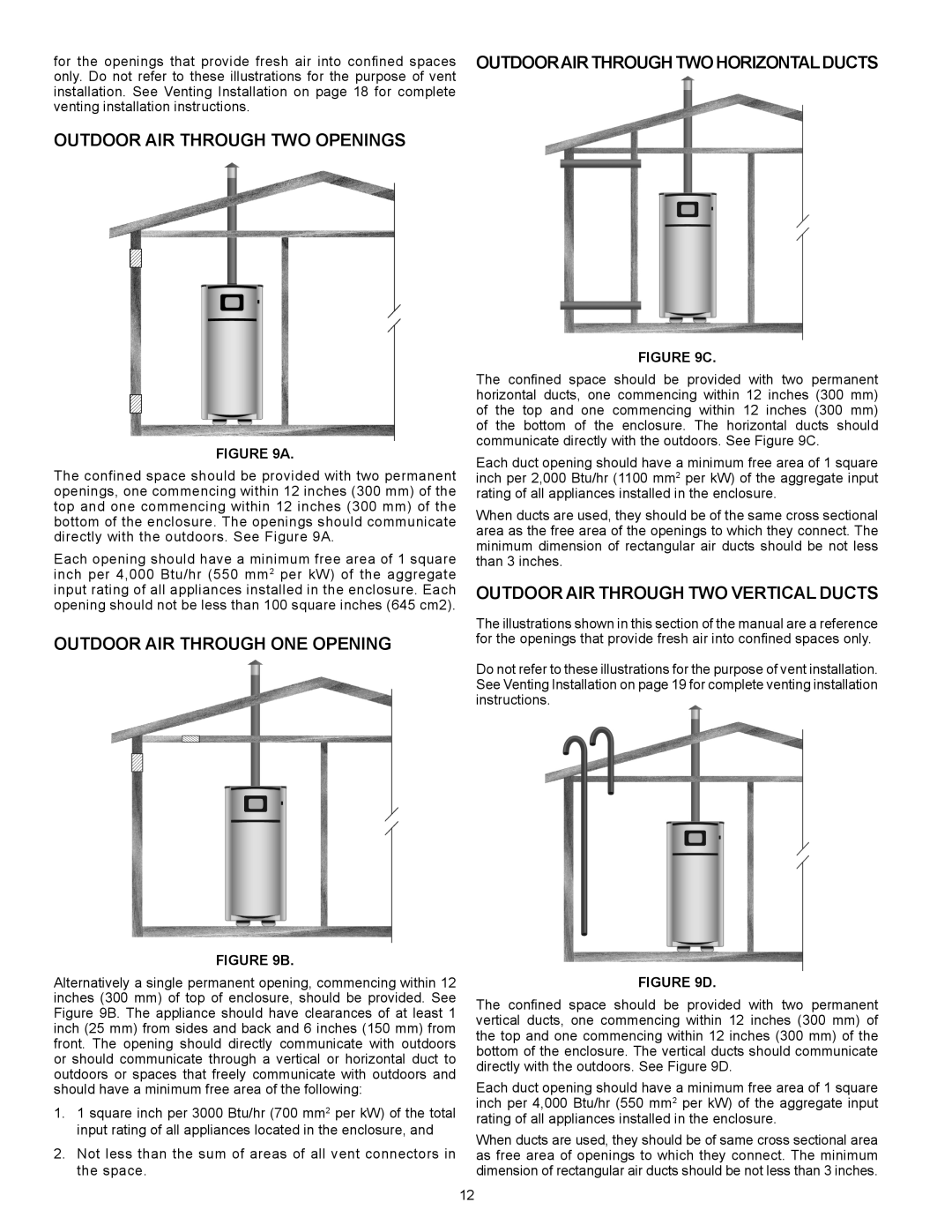
Outdoor Air Through Two Openings

FIGURE 9A.

The confined space should be provided with two permanent openings, one commencing within 12 inches (300 mm) of the top and one commencing within 12 inches (300 mm) of the bottom of the enclosure. The openings should communicate directly with the outdoors. See Figure 9A.

Each opening should have a minimum free area of 1 square inch per 4,000 Btu/hr (550 mm2 per kW) of the aggregate input rating of all appliances installed in the enclosure. Each opening should not be less than 100 square inches (645 cm2).

Outdoor Air Through One Opening

FIGURE 9B.

Alternatively a single permanent opening, commencing within 12 inches (300 mm) of top of enclosure, should be provided. See Figure 9B. The appliance should have clearances of at least 1 inch (25 mm) from sides and back and 6 inches (150 mm) from front. The opening should directly communicate with outdoors or should communicate through a vertical or horizontal duct to outdoors or spaces that freely communicate with outdoors and should have a minimum free area of the following:

1.1 square inch per 3000 Btu/hr (700 mm2 per kW) of the total input rating of all appliances located in the enclosure, and

2.Not less than the sum of areas of all vent connectors in the space.

OutdoorAir Through Two HorizontalDucts

FIGURE 9C.

The confined space should be provided with two permanent horizontal ducts, one commencing within 12 inches (300 mm) of the top and one commencing within 12 inches (300 mm) of the bottom of the enclosure. The horizontal ducts should communicate directly with the outdoors. See Figure 9C.

Each duct opening should have a minimum free area of 1 square inch per 2,000 Btu/hr (1100 mm2 per kW) of the aggregate input rating of all appliances installed in the enclosure.

When ducts are used, they should be of the same cross sectional area as the free area of the openings to which they connect. The minimum dimension of rectangular air ducts should be not less than 3 inches.

Outdoor Air Through Two Vertical Ducts

The illustrations shown in this section of the manual are a reference for the openings that provide fresh air into confined spaces only.

Do not refer to these illustrations for the purpose of vent installation. See Venting Installation on page 19 for complete venting installation instructions.

FIGURE 9D.

The confined space should be provided with two permanent vertical ducts, one commencing within 12 inches (300 mm) of the top and one commencing within 12 inches (300 mm) of the bottom of the enclosure. The vertical ducts should communicate directly with the outdoors. See Figure 9D.

Each duct opening should have a minimum free area of 1 square inch per 4,000 Btu/hr (550 mm2 per kW) of the aggregate input rating of all appliances installed in the enclosure.

When ducts are used, they should be of same cross sectional area as free area of openings to which they connect. The minimum dimension of rectangular air ducts should be not less than 3 inches.

12

Page 12
Image 12
A.O. Smith VB/VW- 1000, VB/VW- 750 instruction manual Outdoor Air Through Two Openings, Outdoor Air Through One Opening

VB/VW- 1000, VB/VW- 750 specifications

A.O. Smith is a renowned name in the water heating industry, and their VB/VW-750 and VB/VW-1000 models reflect the cutting-edge advancements in both design and functionality. These commercial water heaters stand out due to their innovative features and robust characteristics, making them ideal solutions for various applications in commercial settings.

The VB/VW-750 and VB/VW-1000 models are designed with high efficiency in mind. They utilize advanced heat transfer technology that maximizes energy use, translating to significant savings on utility bills. These units are engineered to deliver consistent hot water supply, essential for businesses such as restaurants, hotels, and manufacturing facilities where extensive hot water demands are necessary.

One of the standout features of the VB/VW models is their high recovery rate. This means they can produce a large volume of hot water within a short period, catering to peak demand times without compromising performance. Additionally, the units come equipped with a durable tank made from high-quality materials to resist corrosion, which ensures a long lifespan and reliability in service.

The VB/VW-750 and VB/VW-1000 are also equipped with advanced control systems. These systems provide precise temperature regulation, improving safety and energy efficiency. The smart pumping system further enhances performance by optimizing water flow and reducing energy consumption during operation.

Maintenance and serviceability are key characteristics of these models. They feature easy access to critical components, allowing for quick inspections and repairs. This design consideration minimizes downtime, which is crucial for any business reliant on continuous hot water supply.

Both models are compliant with various industry standards, including energy efficiency regulations. A.O. Smith has focused on ensuring these water heaters not only meet but exceed these requirements, contributing to sustainability efforts.

In summary, the A.O. Smith VB/VW-750 and VB/VW-1000 models combine efficiency, reliability, and ease of maintenance. Their advanced features and cutting-edge technologies make them a top choice for commercial hot water applications, positioning A.O. Smith as a leader in the water heating industry. With their strong performance and durability, these models are designed to meet the demands of modern businesses while providing peace of mind regarding hot water availability.