Disassembly Procedure Flowchart
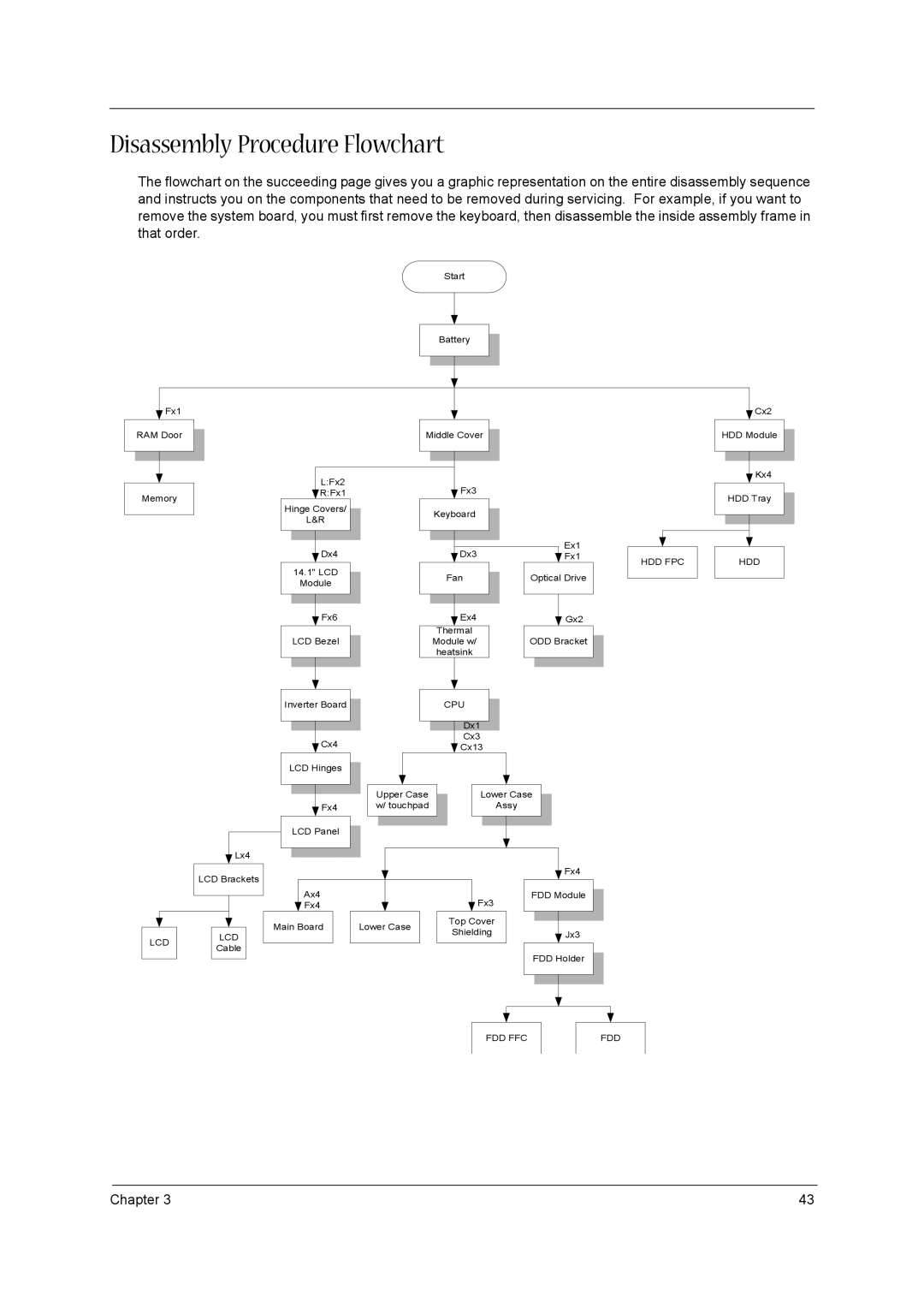
The flowchart on the succeeding page gives you a graphic representation on the entire disassembly sequence and instructs you on the components that need to be removed during servicing. For example, if you want to remove the system board, you must first remove the keyboard, then disassemble the inside assembly frame in that order.
Start
Battery
Fx1
RAM Door
Middle Cover
Cx2
HDD Module
Memory
L:Fx2
![]() R:Fx1
R:Fx1
Hinge Covers/
L&R
![]() Dx4
Dx4
14.1" LCD
Module
Fx6
LCD Bezel
Inverter Board
Cx4
LCD Hinges
Fx4
LCD Panel
|
| Fx3 |
|
|
|
|
|
|
|
|
|
|
|
|
| ||
|
|
|
|
|
|
|
|
|
| Keyboard |
|
|
|
|
|
| |
|
|
|
|
|
|
| ||
|
|
|
|
|
|
| Ex1 |
|
|
|
|
|
|
|
|
| |
|
|
|
|
| ||||
|
| Dx3 |
|
|
| Fx1 |
| |
| Fan |
|
| Optical Drive |
| |||
|
|
| ||||||
|
|
|
|
|
|
|
|
|
|
|
|
|
|
|
|
|
|
|
| Ex4 |
|
|
| Gx2 |
| |
|
|
|
|
|
| |||
| Thermal |
|
|
|
|
|
| |
| Module w/ |
|
|
| ODD Bracket |
| ||
| heatsink |
|
|
|
|
|
| |
|
|
|
|
|
|
|
|
|
|
|
|
|
|
|
|
|
|
CPU
Dx1
Cx3
![]() Cx13
Cx13
Upper Case |
| Lower Case |
| |
w/ touchpad |
| Assy |
| |
|
|
|
|
|
|
|
|
|
|
Kx4
HDD Tray
HDD FPC |
| HDD |
|
|
|
Lx4
|
|
| LCD Brackets | |||
|
|
|
|
|
|
|
|
|
|
|
|
| |
|
|
|
|
|
|
|
|
|
|
|
|
|
|
LCD |
|
| LCD |
| ||
|
| Cable |
| |||
|
|
|
|
| ||
|
|
|
|
|
|
|
|
|
|
|
|
|
|
|
|
|
| Fx4 | |
|
|
|
|
|
|
|
|
|
|
| ||
|
|
|
|
|
|
|
|
|
|
|
| |
| Ax4 |
|
|
|
| Fx3 |
|
| FDD Module |
| ||
|
|
|
|
| ||||||||
| Fx4 |
|
|
|
|
|
|
|
|
| ||
Main Board |
| Lower Case |
| Top Cover |
|
|
|
|
| |||
|
|
|
|
|
|
| ||||||
|
| Shielding |
|
|
| Jx3 | ||||||
|
|
|
|
|
|
|
|
| ||||
|
|
|
|
|
|
|
|
|
|
|
|
|
FDD Holder
FDD FFC
FDD
Chapter 3 | 43 |