Aspire 1360/1520 Series
Service Guide
Revision History
Date Chapter Updates
Copyright
Conventions
Preface
Page
Table of Contents
Jumper and Connector Locations
Page
Chapter
Features
Expansion
Yuhina 4W Block Diagram
Top View
Board Layout
Bottom View
Description
Panel
Front View
Icon Item/ Port Description
Left view
Item/ Port Description
Right View
Port Description
Rear Panel
Bottom View
Icon Function Description
Indicators
Lock key Description
Keyboard
Special keys
Embedded numeric keypad
Desired access Num lock on Num lock off
Keys Description
Windows keys
Hot Keys
Click on the Language tab and click on Details
Launch Keys
Specification
Hardware Specifications and Configurations
System Board Major Chips
Processor
System Memory
Second Level Cache
Memory Combinations
LAN Interface
Hard Disk Drive Interface
Modem Interface
VIA VT8235CE
MK4025GAS MK6021GAS
DVD-ROM Interface
Items Specification
CD-ROM Interface
KME UJDA750
Combo Drive Interface
IDE
DVD Dual Interface
Ultra Speed CD-RW
Low Speed CD-RW
High Speed CD-RW
Video Interface
VGA Display Resolution
Audio Interface
CRT Display Resolutions
LCD Display Resolution
Resolution Bit Bits 256colors Hi color True color
Video Memory
USB Port
Battery
Pcmcia Port
Keyboard
AC Adapter
Environmental Requirements
Power Management
Mechanical Specification
Chapter
System Utilities
Bios Setup Utility
Navigating the Bios Utility
Parameter Description
Information
Main
Advanced Security Boot Exit
Post
Parameter Description Format/Option
Parameter Description Options
Advanced
IRQ3/IRQ4
DMA/DMA3
DMA3/DMA1
Security
Boot Exit
Parameter Description Option
Clear or Set
Removing a Password
Page
+Hard Drive
Boot
Exit
Info Main Advanced Security Boot
Bios Flash Utility
Machine Disassembly and Replacement
Before You Begin
General Information
HDD
Disassembly Procedure Flowchart
LCD
Screw List
Screw MAC Flat M2.5*L4 NI Nylok
Screw M2*3 Nylon 1JMCPC
Removing the Battery
Removing the Memory Module
Removing the Wireless LAN Board and the Modem Board
Disassembling the Hard Disk Drive Module
Removing the Hard Disk Drive Module
Removing the Launch Board
Removing the LCD Module
Removing the Middle Cover
Removing the LCD Module
Chapter
Removing the Inverter Board 15 LCD
Disassembling the LCD Module
Removing the LCD Bezel
Removing the 15 TFT LCD
Removing the LCD Coaxial Cable
Removing the LCD Brackets
Removing the LCD Hinges
Disassembling the Main Unit
Removing the RTC Battery
Removing the Keyboard
Removing the Middle Cover Hook /Fan
Removing the Processor
Removing the Thermal Module
Removing the Upper Case Assemly
Installing the Processor
Removing the Touchpad Cable
Removing the Touchpad Board
Removing the CPU Heatsink Plate
Removing the VGA Thermal Plate
Removing the ODD Module2
Removing the Second Fan Bracket
Removing the ODD Module1
Removing the Main Board
Removing the HDD Bracket
Removing the I/O Port Bracket
Removing the DC Board
Removing the Pcmcia Slot
Removing the Speaker Set
Base Unit to Wireless Unit
System Upgrade Procedure
Symptoms Verified Go To
Troubleshooting
External Diskette Drive Check
System Check Procedures
External CD-ROM Drive Check
Keyboard or Auxiliary Input Device Check
Memory check
Power System Check
Check the Power Adapter
Touchpad Check
Check the Battery Pack
Power-On Self-Test Post Error Message
Error Code List
Index of Error Messages
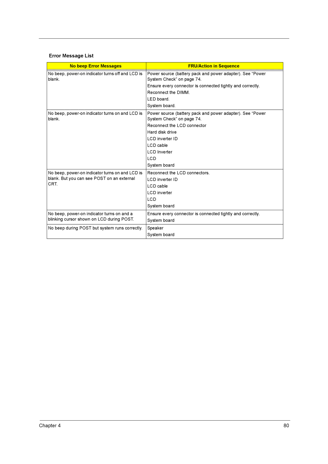
Error Message List
Error Codes Error Messages
CPU ID
Cmos Dimm
CRT
No beep Error Messages FRU/Action in Sequence
Code Beeps Post Routine Description
Post Code
Chapter
Code Beeps Post Routine Description
Code Beeps For Boot Block in Flash ROM
LCD-Related Symptoms
Index of Symptom-to-FRU Error Message
Indicator-Related Symptoms
Power-Related Symptoms
Memory-Related Symptoms
PCMCIA-Related Symptoms
Speaker-Related Symptoms
Power Management-Related Symptoms
Modem-Related Symptoms
Peripheral-Related Symptoms
Keyboard/Touchpad-Related Symptoms
Intermittent Problems
Dimm
Undetermined Problems
CD to Disk Recovery
How to Build Napp Master Hard Disc Drive
Chapter
Page
Disk to Disk Recovery
Page
Chapter
Page
Chapter
Lout
LIN1
JK1
FAN1
SW1-8 SW2-7 SW3-6
SW Settings
FRU Field Replaceable Unit List
Aspire 1360/1520 Exploded Diagram
Aspire
MODEM/BLUETOOTH Board Ambit
Wireless LAN Board 802.11BG
Power Cord 10A 125V US
Cover Switch Cable
Hinge CAP Left
Upper Case W/COVERSWITCH
HDD Support Bracket
Optical Device Support
Wireless Antenna LEFT/RIGHT
Bluetooth Antenna
Lower Case W/DIMM Cover
Speaker W/O MDC Cover Dimm Cover W/SCREWS
CPU Thermal Plate
HDD Bracket
CPU Heatsink W/FAN
VGA Thermal Plate
German Keyboard Darfon NSK-ACD0K
Keyboard Darfon NSK-ACD0G
Korean Keyboard Darfon NSK-ACD0L
Greek Keyboard Darfon NSK-ACD0M
LCD Bracket Assembly 15.1 Left
LCD Bracket Assembly
LCD Bracket 15.4 Right
Right LCD Bracket 15.4 Left
Touchpad Button
Hinge Pack 15 LEFT/RIGHT
LCD Screw CAP Lower
LCD Screw Rubber Upper
DVD-RW Module
CDRW/DVD Combo Module
CDRW/DVD Combo Drive
Panasonic UJDA760 DVD-RW 4X QSI SDW-042 Dual
Screw M2.5*4L NI
Scrw M2.5*3 Wafer NI
Chapter 112
42.A30V1.002 113 Chapter
Chapter 114
Wireless Antenna Right Black
Italian
Antennahitachi LCD Module 15.4 Wxga W/O
French Keyboard Darfon NSK-ACD0G
Antennaqdi LCD Module 15.4 Wxga W/O
Antennaau LCD Module 15.4 Wxga W/O
Mainboard Yuhina 4 W/LAUNCH
M470L6524BT0-CB3 Optical Drive
Chapter 120
121 Chapter
Appendix a
Wireless
Model Name Definition
Memory
ODD/Card
Model
Appendix B
Test Compatible Components
Microsoft Windows XP Environment Test
Specifications
Isdn
Sanyo BTP-60A1
Appendix B
PCMCIA-SCSI
Pcmcia Pcmcia ATA
Pcmcia USB
119
Appendix C Online Support Information
121
Index
Bios
Pcmcia