Manuals
/
Acer
/
Computer Equipment
/
Laptop
Acer
3300
manual
Modem Board Connector MDC MDC Cable Connector RING1 Chapter
Models:
3300
1
12
100
100
Download
100 pages
51.94 Kb
9
10
11
12
13
14
15
16
Troubleshooting
Code list
DiagramSystem Block
Bluetooth
Password
Euro symbol
Indicators
Removing the Wireless LAN Card
Dimension
LCD-Related Symptoms
Page 12
Image 12
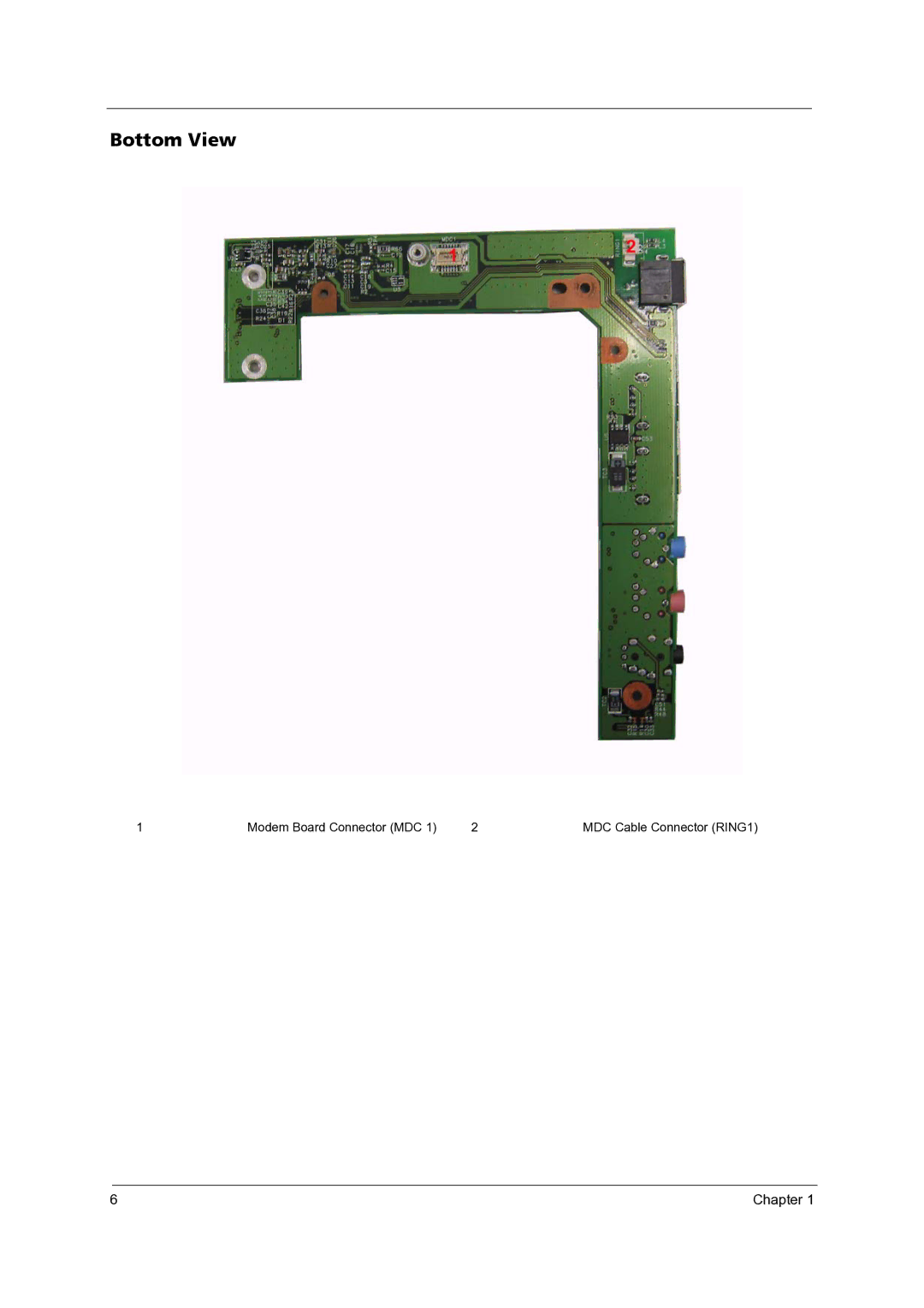
Bottom View
1
Modem Board Connector (MDC 1)
2
MDC Cable Connector (RING1)
6
Chapter 1
Page 11
Page 13
Page 12
Image 12
Page 11
Page 13
Contents
Acer TravelMate 3300/Extensa 3100 Series
Date Chapter Updates
Revision History
Copyright
Disclaimer
Conventions
Screen Messages
Preface
Page
Features
Chapter
Dimensions and weight
Mainboard Layout
Top View
Bottom View
IO Board Layout
Modem Board Connector MDC MDC Cable Connector RING1 Chapter
DiagramSystem Block
Myna
Outlook View
Front View
Description
Closed front view
Left View
Icon Description
Right View
Rear View
Bottom View
Indicators
Easy-launch button Default application
Easy-launch buttons
Touchpad
Touchpad Basics
Page
Using the Keyboard
Desired Access Num Lock On Num Lock Off
Lock Keys and embedded mumeric keypad
Windows Keys
Hot Keys
Key Icon Description
Special Key
Hot Key Icon Function Description
Euro symbol
Using System Utilities
Acer eManager
Launch Manager
Hardware Specifications and Configurations
Processor
System Board Major Chips
L2 Cache
Modem/Bluetooth Interface
System Memory
LAN Interface
USB Port
Pcmcia Port
Keyboard
Battery
LCD 14.1 Wxga
Hard Disk Drive Interface
AC Adapter
Power Management
Dimensions and Weight
Acpi Mode Power Management
Details
Environmental Requirements
HDD Interface
Chapter
Bios Setup Utility
Function
Main Advanced Security Boot Exit
Information
Parameter Description
Advanced Security Boot Exit
Main
Adjustable during Post
Advanced
Description Option
Auto
ECP
Security
Parameter Description Option
Set Supervisor/User Password
Disabled
Characters 0-9,A-Z not case sensitive
Enter
Setup Notice Changes have been saved Continue
Boot
Parameter Description
Information Main Security Boot
Exit
Machine Disassembly and Replacement
General Information
Before You Begin
Disassembly Procedure Flowchart
Screw List
Description Part Number
Removing the Battery Pack
Removing the Wireless LAN Card
Removing the Memory and the HDD Module
Removing the LCD Module
Chapter
Disassembling the Lower Case Assembly
Disassembling the Main Unit
Chapter
Disassembling the Upper Case Assembly
Disassembling the LCD Module
Page
Disassembling the External Modules
Disassembling the HDD Module
Troubleshooting
System Check Procedures
External Diskette Drive Check
External CD-ROM Drive Check
Keyboard or Auxiliary Input Device Check
Power System Check
Memory check
Touchpad Check
Power-on Self-Test Error Messages
Index of Error Messages
Error Code List
Error Message List
Error Codes Error Messages
CPU ID
No beep Error Messages FRU/Action in Sequence
LCD
Phoenix Bios Beep Codes
Code Beeps Post Routine Description
Code Beeps Post Routine Description
Chapter
Code Beeps Post Routine Description
Index of Symptom-to-FRU Error Message
LCD-Related Symptoms
Indicator-Related Symptoms
Power-Related Symptoms
PCMCIA-Related Symptoms
Memory-Related Symptoms
Speaker-Related Symptoms
Power Management-Related Symptoms
Peripheral-Related Symptoms
Keyboard/Touchpad-Related Symptoms
Modem-Related Symptoms
Intermittent Problems
Undetermined Problems
Dimm
Chapter
Jumper and Connector Locations
JK1
INTMIC1
MDC1
Switch Settings
Switch Settings
Switch Function
Chapter
FRU Field Replaceable Unit List
Exploded Diagram
Image Part Name Description Acer P/N
Battery Pack LI+ BTY Pack LI+ 6C
Modem Cable Cable Modem US W
Touchpad Plate Assy T/P Plate
HDD Cover Assy HDD Cover
DVD-RW Drive Dual PAN/UJ-840B LF
HDD Mylar W Assy HDD Chassis
Danish TM3300 Keyboard
LCD Bezel
MYNA2 LCD Bracket Left
Glare 420G LCD 14.1 Wxga QDI
Sdimm 512M SODIMM512MHYS64T
HDD Sponge HDD Sponge MYNA-2
Top
Page
Image
Contents