2.Replace the two screws to secure the cover in place.
3.Replace the memory cover as shown.
4.Replace the two screws to secure the cover in place.
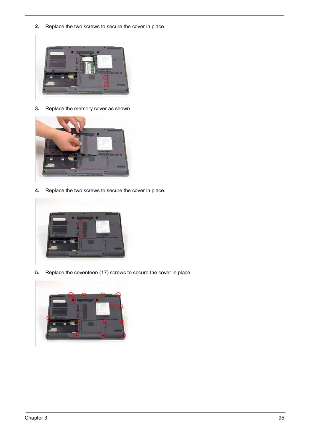
5.Replace the seventeen (17) screws to secure the cover in place.
Chapter 3 | 95 |
2.Replace the two screws to secure the cover in place.
3.Replace the memory cover as shown.
4.Replace the two screws to secure the cover in place.
5.Replace the seventeen (17) screws to secure the cover in place.
Chapter 3 | 95 |