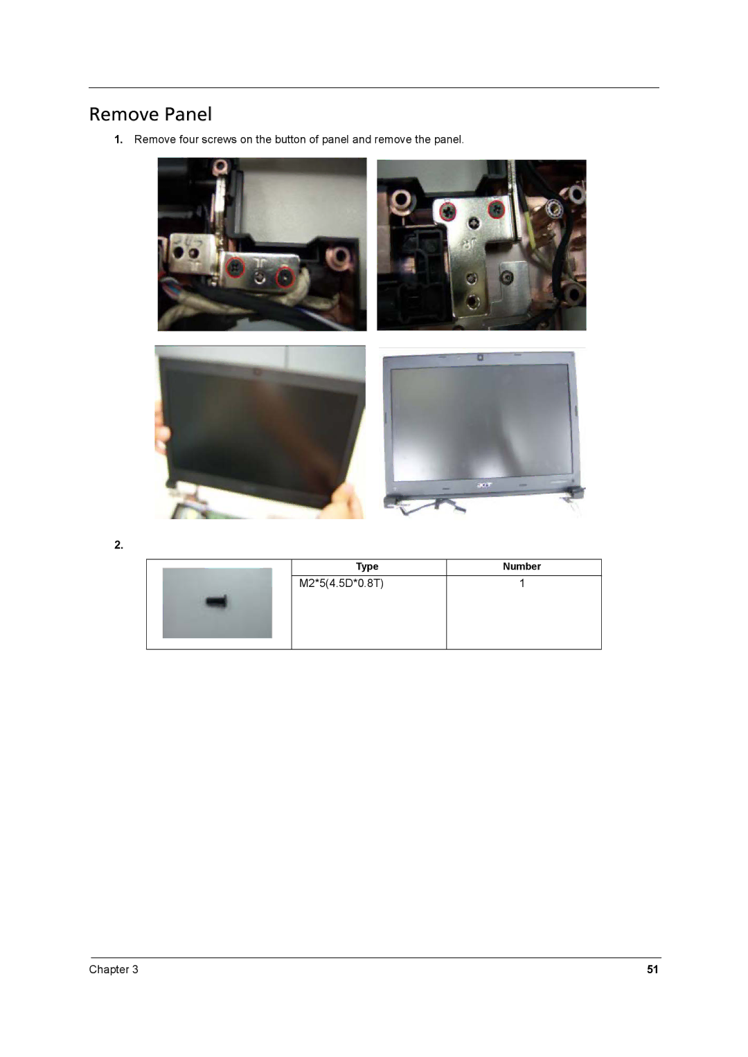
Manuals
/
Brands
/
Computer Equipment
/
Laptop
/
Acer
/
Computer Equipment
/
Laptop
Acer
8531, 8571
- page 59
1
59
98
98
Download
98 pages, 7.78 Mb
Chapter 3
51
Remove Panel
1.
Remove four screws on the button of panel and remove the panel.
2.
Ty
p
e N
u
m
b
e
r
M2*5(4.5D*0.8T) 1
Contents
Main
Page
Copyright
Disclaimer
Conventions
Preface
Page
Table of Contents
System Specifications 1
System Utilities 27
Machine Disassembly and Replacement 37
Troubleshooting 55
Table of Contents
Jumper and Connector Locations 73
FRU (Field Replaceable Unit) List 75
System Specifications
Chapter 1
Features
Operating system
Platform
Storage subsystem
Communication
Privacy control
Dimensions and weight
Power subsystem
Environment
4Chapter 1
System Block Diagram
PLL
CPU
Board Layout
Top View
Bottom View
Your Acer Notebook tour
Top View
Closed Front View
Rear view
Left View
Right View
Base view
Touchpad Basics (with fingerprint reader)
Touchpad basics (with two-click buttons)
Using the Keyboard
Lock Keys and embedded numeric keypad*
Windows Keys
Hot Keys
Using the system utilities
Acer Bio-Protection (only for certain models)
Acer GridVista (dual-display compatible)
Acer Backup Manager
Power management
Acer PowerSmart key
Acer eRecovery Management
Burn backup discs
Restore
Restore Windows Vista from backup discs
Hardware Specifications and Configurations
Bluetooth Interface
Hard Disk Drive Interface
Audio Interface
LCD panel
Card Slot WebCAM
Keyboard
I/O
LED Status Indicator
Button
Software
Page
System Utilities
Chapter 2
BIOS Setup Utility
Invoking BIOS Setup
Information
Main
Page
Page
Setting a Password
Removing a Password
Changing a Password
Page
Exit
BIOS Flash Utility
Chapter 3
Machine Disassembly and Replacement
Page
Page
Page
Page
Page
Page
Page
Page
Page
Page
Page
Page
Page
Page
Page
Page
Page
Troubleshooting
Chapter 4
System Check Procedures
External Diskette Drive Check
External CD-ROM Drive Check
Keyboard or Auxiliary Input Device Check
Memory check
Power System Check
Check the Power Adapter
Check the Battery Pack
Touchpad Check
Power-On Self-Test (POST) Error Message
Index of Error Messages
Error Code List
Error Message List
Page
Error Message List
InsydeH2O BIOS Beep Codes
Page
Page
Page
Index of Symptom-to-FRU Error Message
LCD-Related Symptoms
Power-Related Symptoms
Indicator-Related Symptoms
PCMCIA-Related Symptoms
Memory-Related Symptoms
Power Management-Related Symptoms
Speaker-Related Symptoms
Peripheral-Related Symptoms
Keyboard/Touchpad-Related Symptoms
Modem-Related Symptoms
Page
Undetermined Problems
Jumper and Connector Locations
Chapter 5
Top View
Bottom View
FRU (Field Replaceable Unit) List
Chapter 6
76 Chapter 6
TravelMate 8571/8531 Exploded Diagram
Page
Page
Chapter 6 79
TravelMate 8571/8531 FRU List
Accessory
Board
Adapter
Battery
80 Chapter 6
Cable
Chapter 6 81
82 Chapter 6
Chapter 6 83
Camera
CASE/COVER/BRACKET ASSEMBLY
DVD RW DRIVE
84 Chapter 6
Chapter 6 85
HDD/SSD
HEATSINK
86 Chapter 6
KEYBOARD
Chapter 6 87
LCD
MIAN BOARD
88 Chapter 6
MEMORY
MICROPHONE
MISCELLANEOUS
Chapter 6 89
SCREW
SPEAKER