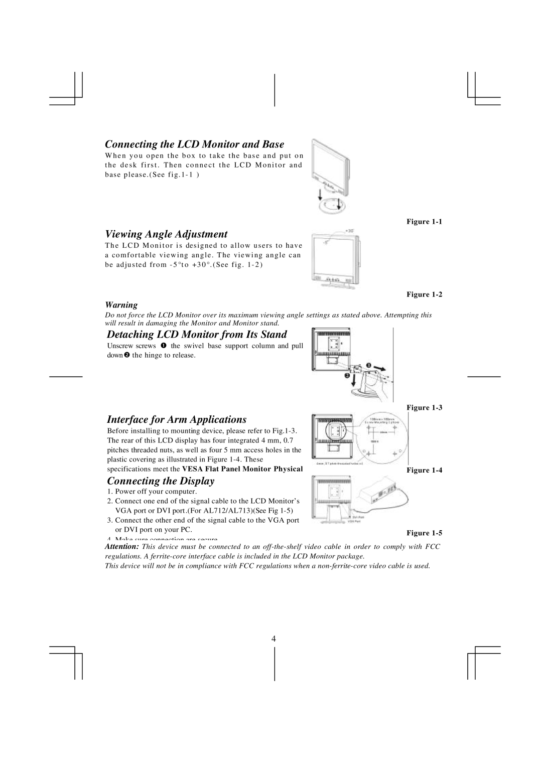
Connecting the LCD Monitor and Base
W h e n y o u o p e n t h e b o x t o t a k e t h e b a s e a n d p u t o n t h e d e s k f i r s t . T h e n c o n n e c t t h e L C D M o n i t o r a n d base please . (See fig . 1 - 1 )
Figure
Viewing Angle Adjustment
T h e L C D M o n i t o r i s designed to allow users to have
ac o m f o r t a b l e v i e w i n g a n g l e . T h e v i e w i n g a n g l e c a n be adjusted from - 5 °t o +3 0 °. (See fig . 1 - 2 )
Figure
Warning
Do not force the LCD Monitor over its maximum viewing angle settings as stated above. Attempting this will result in damaging the Monitor and Monitor stand.
Detaching LCD Monitor from Its Stand
Unscrew screws Œ the swivel base support column and pull down• the hinge to release.
Interface for Arm Applications
Before installing to mounting device, please refer to
Connecting the Display
1.Power off your computer.
2.Connect one end of the signal cable to the LCD Monitor’s VGA port or DVI port .(For AL712/AL713)(See Fig
3.Connect the other end of the signal cable to the VGA port
or DVI port on your PC.
4. Make sure connection are secure.
Attention: This device must be connected to an
This device will not be in compliance with FCC regulations when a
4